


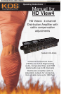
HD View4
7
KD-ADA4
Sales Support: 718-796-7178 Ext. 10 Michael@keydigital.com
Marketing Support: 718-796-7178 Ext. 11 Masha@keydigital.com
HD View4
Technical Specifications
www.keydigital.com
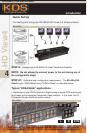
STEP D: Adjust the front-panel potentiometers to compensate for the long
cable Output runs of Y, Pr, Pb, and CV (Composite Video).
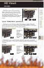
• The front panel of the KD-ADA4 HD View4 unit has four groupings, labeled
Output 1 through Output 4, which match the physical distribution Output Groups
1-4.
• You will need an Ohmmeter set in the range of 75 Ohms. You will need to per-
form the following procedure for each signal (CV, Pb, Y, Pr) for each Output
Group (1-4).
• For the PCMD4 Mode distribution of PCM digital audio, be sure to set all KD-
ADA4 Resistance values to 75 Ohms in the following procedures.
NOTE: POWER MUST BE TURNED OFF FOR THE KD-ADA4 AND ALL
OTHER UNITS CONNECTED TO THE I/O CABLES WHEN PERFORMING
THESE STEPS AND DIP SWITCHES SET TO ADA4 MODE.
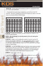
STEP D1: Determine the resistance of each cable at the KD-ADA4 HD View4
end, when the cable is terminated at its destination. Use your Ohmmeter to
measure the resistance of the cable, by removing the cable from the back of the
KD-ADA4 HD View4 unit. This measurement is from the center point of the RCA
jack to the outside of the RCA jack. Make note of this resistance value, called
"Rload".
STEP D2: Determine the resistance of the KD-ADA4 HD View4. It is a simple
calculation, KD-ADA4 Resistance = 150 Ohms - Rload.
STEP D3: Set the KD-ADA4 HD View4 resistance. First, insert the Ohmmeter
cables into the top and bottom test sockets on the front of the KD-ADA4 HD
View4 for the signal corresponding to the cable you measured. Using a small,
slotted screwdriver or other implement, set the corresponding potentiometer (to
the lower left of each signal’s Ohmmeter test socket) to the value calculated
above for KD-ADA4 Resistance by comparing the Ohmmeter value to the desired
value for KD-ADA4 Resistance.
STEP D4: Repeat the above procedure in its entirety for each output cable.
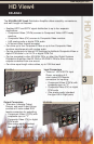
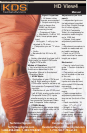
Inputs (on back panel):
• There is 1 HDTV/SDTV Input
Group, consisting of 6 color-
coded RCA female connectors for
inputting:
• Component Video (YPrPb) with
composite sync on "Y"
• Composite Video (CV) or digital
PCM audio
• One analog audio (standard
line-type Left & Right pairs)
Outputs (on back panel):
• There are 4 discrete Output Groups, and
each Output Group consists of 6
color-coded RCA female connectors for
outputting:
• Component Video (YPrPb) with
composite sync on "Y"
• Composite Video (CV) or digital PCM
audio
• One analog audio (standard line-type Left
& Right pairs)