


KDC-MP925/W8027
7
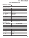
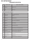
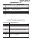
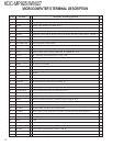
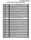
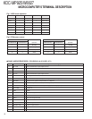
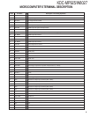
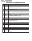
Pin No. Pin Name I/O Description / Processing Operation
Fig
62 MOSW O CD mechanism motor driver SW (LOADING, EJECT, Brake : H)
63 FPM MOTOR B O FPM mechanism (Slider) control terminal 2
64 FPM MOTOR F O FPM mechanism (Slider) control terminal 2
65 FPM MOTOR O O FPM mechanism (Angle) control terminal 2
66 FPM MOTOR C O FPM mechanism (Angle) control terminal 2
67 O DATA I/O External display DATA terminal 2
68 O CLK I/O External display CLK terminal
69 O CE I/O External display chip enable terminal
70 M MUTER I Mute request from CD mechanism (Rch ON : L)
71 AVDD - AVR 5V
72 AVSS - GND
73 AVREF I Connect to P-ON (29PIN)
74 M MUTEL I Mute request from CD mechanism (Lch ON : L)
75 PAN DET I PANEL, E2PROM detection terminal (With panel : L, Without : H)
76 PHONE I PHONE detection terminal (TEL MUTE : 1V or less, NAVI MUTE : 2.5V or more)
77 FPM SW4 I
FPM mechanism position detect/ CD Mechanism detection terminal
2
(3.75V or more : No mechanism, 1.25V or more : H, Less than 1.25V : L)
78 FPM SW1 I FPM mechanism position detect terminal 2
79 FPM SW2 I FPM mechanism position detect terminal 2
80 FPM SW3 I FPM mechanism position detect terminal 2
81 FPM PHOUT I FPM mechanism position detect terminal (2.2V or more : H) 2
82 S METER I S meter detection terminal
83 NOISE I FM noise detection terminal
84 IFC OUT I Front end IFC OUT input terminal (Receiving station : 2.5V or more)
85 POWER DET I Audio power IC DC offset detection
86 CD SW4 I 8cmDISC detection terminal (8cmDISC : L)
87 R CLK I RDS decoder clock input terminal
88 LX REQ S I Receive request from external slave unit (Request : L)
89 SC REQ I Communication request from panel microprocessor
90 CD SW1 I LOADING SW detection terminal (LOADING start, POWER OFF : L)
91 CD SW2 I 12cmDISC detection terminal (12cmDISC, POWER OFF : L)
92 R QUAL I RDS decoder QUAL input terminal
93 R DATA I RDS decoder DATA input terminal
94 LX DATA S I Data input from external slave unit
95 LX DATA M O Data output to external slave unit
96 LX CLK I/O Clock input/ output with external slave unit
97 PAN RX I Data input from panel microprocessor
98 PAN TX O Data output to panel microprocessor
99 WOW MODE1 O WOW control terminal
100 PLL CLK I/O Clock input/ output to Tuner front-end 1
MICROCOMPUTER’S TERMINAL DESCRIPTION