


KDC-MP925/W8027
5
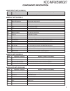
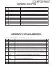
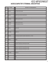
Ref No. Application / Functions Operation / Condition / Compatibility
Q27 BU detector When Q27 base level goes H, Q27 turned ON
Q29 ACC detector When Q29 base level goes H, Q29 turned ON
Q30,31 Muting driver When base level goes L, muting driver is turned ON
Q201 Buffer Noise detect buffer amp
Q202 E-VOL muting SW When Q202 base level goes H, muting SW is turned ON
Q203~208
Pre-out muting SW When base level goes H, Pre-output is muted
Q210 AGC For AGC for spectrum analyzer
Q303,304 AM +B SW When Q303 base level goes H, AM +B is out to tuner unit
Q305 Buffer Composite signal buffer for RDS
Q501 E2P 5V SW When Q501 base level goes L, E2P 5V is out for E2PROM
Q502,503 Panel 5V SW When Q503 base level goes H, Panel 5V is out
Q603 SW When Q603 base level goes H, Q603 is turned ON
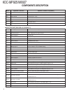
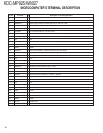
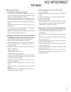
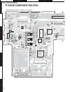
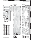
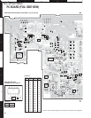
COMPONENTS DESCRIPTION
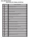
● SYSTEM MICROPROCESSOR : UPD703030GC041 (X34-303 : IC1)
Pin No. Pin Name I/O Description / Processing Operation
Fig.
1 PLL DATA I/O Data input/output terminal for Tuner front-end
2 AM+B I/O AM+B (AM operation : H)
3 (FM+B) O FM+B (FM operation : H, Last FM : H with RDS, RBDS model)
4PAN E2P DATA I/O Variable illumination D/A converter, E2PROM DATA terminal
5PAN E2P CLK I/O Variable illumination D/A converter, E2PROM CLK terminal
6 EVDD - VDD 5V
7 EVSS - GND
8 AFS O Time constant switching for noise detection (FM seek, AF search, AUTO 0 : L, Receiving : H)
9 BEEP O BEEP audio output terminal
10 REMO I Remote control input terminal
11 P MUTE O Audio power IC muting control terminal (POWER OFF, ALL OFF, TEL MUTE : L)
12 SVR O Audio power IC SVR discharge circuit control terminal
13 IC2 SDA I/O CD mechanism, IC2, IC5, ROM correction DATA line
14 IC2 CLK I/O CD mechanism, IC2, IC5, ROM correction CLOCK line
15 P STBY O Audio power IC Stand-by terminal (POWER IC ON, ALL OFF : H, POWER IC OFF : L)
16 P CON I/O Power control terminal (POWER ON : H, POWER OFF, ALL OFF : Hi-Z)
17 WOW MODE2 O WOW control terminal 1
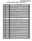
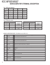
MICROCOMPUTER’S TERMINAL DESCRIPTION