


English
— 22 —
1
2
3
4
5
6
7
8
1
2
3
4
5
6
7
8
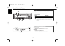
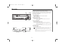
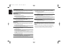
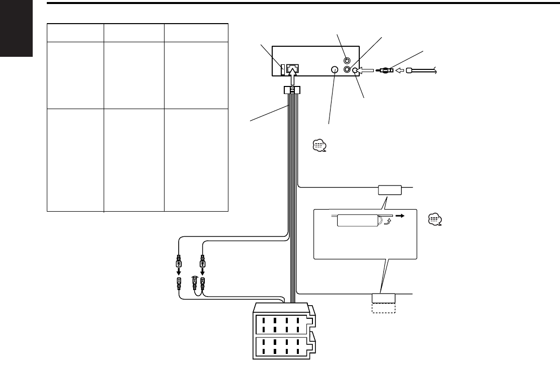
TEL MUTE
P.CONT
ANT. CONT
Rear right
output (Red)
4
10
Rear left
output (White)
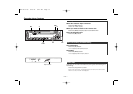
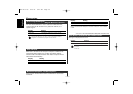
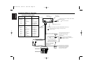
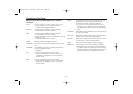
Connector Function Guide
Pin Numbers for
ISO Connectors
Cable Color Functions
External Power
Connector
A–4
A–5
A–7
A–8
Speaker
Connector
B–1
B–2
B–3
B–4
B–5
B–6
B–7
B–8
Yellow
Blue/White
Red
Black
Purple
Purple/Black
Gray
Gray/Black
White
White/Black
Green
Green/Black
Battery
Power Control
Ignition (ACC)
Earth (Ground)
Connection
Rear Right (+)
Rear Right (–)
Front Right (+)
Front Right (–)
Front Left (+)
Front Left (–)
Rear Left (+)
Rear Left (–)
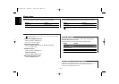
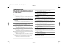
KENWOOD disc changer input (KRC-294A/294G/27A/27G only)
Battery wire (Yellow) 6
Ignition wire (Red) 7
FM/AM antenna input 3
Antenna Cord (ISO) 1
Antenna Conversion Adaptor (ISO–JASO)
(Accessory3) 2
To connect the Disc changer, consult your Disc
changer manual. 15
Wiring harness
(Accessory1) 16
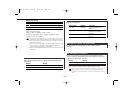
If no connections are
made, do not let the wire
come out from the tab. 18
Power control/ Motor
antenna control wire
(Blue/White) 20
17
TEL mute wire (Brown)
Connect either to the power
control terminal when using
the optional power amplifier,
or to the antenna control
terminal in the vehicle. 23
Connect to the terminal that is
grounded when either the
telephone rings or during
conversation. 21
A–7 Pin (Red) 8
A–4 Pin (Yellow) 9
Connector A
Connector B
Fuse (10A) 13
Connecting Wires to Terminals
To connect the KENWOOD
navigation system, consult your
navigation manual.
B64-2437-00 02.9.24 8:42 PM Page 22