


ENGLISHFRANÇAIS
6 KSC-SW1
Installation / Installation
Operation / Fonctionnement
■ Name of each part / Désignation de chaque pièce ■ Power Indicator
Indicateur de puissance
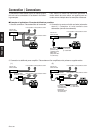
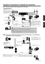
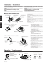
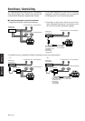
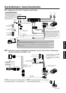
1. Connect the 10-pin connector cord 7, RCA cord 0, and remote control 9
to the speaker unit. (Fig. 1)
(When connecting the speaker input terminal, RCA cord is not necessary)
(The cords to be connected depends on the system. Refer to Connection
of example.)
2. Fix the cords to the speaker unit with fixture C 3, and fix in place with the
machine screws 5. (Fig. 2)
1. Raccordez le cordon de connection à 10 broches 7, le câble RCA 0 et la
télécommande 9 au haut-parleur. (Fig. 1)
(Si vous raccordez à la borne d’entrée du haut-parleur, le câble RCA est
inutile.)
(Le câble à raccorder dépend du système. Reportez- vous aux exemples
de connexions)
2. Fixez les câbles au haut-parleur avec le support C 3, et immobilisez-les
avec les vis à métaux 5. (Fig. 2)
Red glows
(Marche) s'allume
en rouge
Light is OFF
(Arrêt) le voyant
est éteint
[Power ON ]
[Power ON ]
[Power OFF ]
[Power OFF ]
Wooden board
Planche de bois
Carpet
Tapis
REMOTE
LINE IN
POWER/SPEAKER
INPUT
L R
5 Machine screw (M4 × 6) × 2
5 Vis à métaux (M4 × 6) × 2
3 Fixture C
3 Support C
0 RCA cord
0 Câble RCA
9 Remote control
9 Télécommande
Fig. 1 Fig. 2
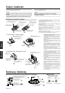
■ Securing method / Méthode de fixation
1. Fixing the cord in place / Fixation du cordon
1. Attach the fixtures A 1 to the speaker unit securely
using the machine screws 5. (Fig. 3)
Be careful so that the conncted cords dosen’t get in
between the speaker unit and fixtures A 1.
2. Place a wooden board of sufficient size, with more than
20mm of thickness, under the carpet of the car. (Fig. 4)
3. Screw the fixtures A 1 firmly onto the wooden board
using the tapping screws 6. (Fig. 4)
1. Accrochez les supports A 1 à l'enceinte fermement à
l'aide des vis à métaux 5. (Fig. 3)
Faites attention de ne pas coincer les câbles raccordés
entre le haut-parleur et les supports A 1.
2. Disposez une planche de bois de taille suffisante, d'une
épaisseur supérieure à 20mm, sous le tapis de la
voiture. (Fig. 4)
3. Vissez fermement les supports A 1 à la planche de
bois grâce aux vis auto taraudeuses 6. (Fig. 4)
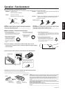
2. Flat installation / Installation à plat
3. Side installation / Installation sur le côté
Before fixing the speaker in its position, be sure to check the sound
while it is connected preliminary.
Caution: ––––––––––––––––––––––––––––––––––––––––––––––
Do not install the speaker on a carpet with long fur.
It will get in the way of the heat escape vent, leading to a fire
hazard.
––––––––––––––––––––––––––––––––––––––––––––––––––––––
Avant de fixer le haut-parleur à endoroit donné, faire une essai de
raccordement pour contrôler le son.
Attention: –––––––––––––––––––––––––––––––––––––––––––––
N'installez pas l'enceinte sur un tapis à longs poils.
Ces derniers pourraient pénétrer dans l'orifice de ventilation,
provoquant des risques d'incendie.
––––––––––––––––––––––––––––––––––––––––––––––––––––––
7 10-pin connector cord
7 Cordon de connection
à 10 broches
9 Remote control
9 Télécommande
0 RCA cord
0 Câble RCA
7 10-pin connector cord
7 Cordon de connection
à 10 broches
6 Tapping screw (φ5 × 16) × 4
6 Vis auto taraudeuse (φ5 × 16) × 4
1. Attach the fixtures B 2 to the speaker unit temporarily,
using the machine screws 5. (Fig. 5)
2. Place a wooden board of sufficient size, with more than
20mm of thickness, under the carpet of the car. (Fig. 6)
3. Screw the fixtures B 2 firmly onto the wooden board
using the tapping screws 6. (Fig. 6)
4. Insert the cushion 4 between the speaker unit and fix-
tures B 2, and fix in place. (Fig. 6)
5. Finally, lightly shake the speaker unit to check that it is
securely fixed.
1. Accrochez les supports B 2 à l'enceinte fermement à
l'aide des vis à métaux 5. (Fig. 5)
2. Disposez une planche de bois de taille suffisante, d'une
épaisseur supérieure à 20mm, sous le tapis de la
voiture. (Fig. 6)
3. Vissez fermement les supports B 2 à la planche de
bois grâce aux vis auto taraudeuses 6. (Fig. 6)
4. Insérez le coussin 4 entre le haut-parleur et les sup-
ports B 2 et fixez-le bien. (Fig. 6)
5. Veuillez enfin secouer légèrement l'enceinte pour
vérifier la solidité de l'ensemble.
6 Tapping screw (φ5 × 16) × 6
6 Vis auto taraudeuse (φ5 × 16) × 6
Carpet
Tapis
Wooden board
Planche de bois
2 Fixture B ×
2
2 Support B × 2
5 Machine screw
(M4 × 6) × 4
5 Vis à métaux
(M4 × 6) × 4
5 Machine screw (M4 × 6) × 4
5 Vis à métaux (M4 × 6) × 4
1 Fixture A × 2
1 Support A × 2
REMOTE CONTROL
Télécommande
Input terminal (RCA pin jack)
Borne d’entrée (Jack RCA)
Power Supply/Control Input / Terminal
(for Speaker Cords)
Borne d'alimentation / commande d'alimen-
tation d'entrée (pour haut-parleurs)
4 5
7
5
Power indicator
(Power display light)
Indicateur de puissance
(Voyant d'alimentation)
6
PHASE
Phase
7
FREQUENCY
Fréquence
7
LEVEL
Niveau
7
Fig. 3
Fig. 4
4 Cushion
4 Coussin
4 Cushion
4 Coussin
2 Fixture B × 2
2 Support B × 2
Fig. 5
Fig. 6
Holes not used
Orifices non utilisés
Holes not used
Orifices non utilisés