KDC-MP925/W8027
4
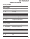
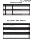
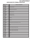
Ref No. Application / Functions Operation / Condition / Compatibility
IC9 AVR 3.3V AVR (IC2 DAC part)
Q1,4 Level shift FET Level shift (3.3V - 5.0V)
Q3,5 Level shift TR Level shift (3.3V - 5.0V)
Q6 Level shift TR Level shift (3.3V - 5.0V)
Q7 Level shift TR Level shift (3.3V - 5.0V)
Q8 APC Auto power control
Q9,10 Switching TR Sub beam delay control switch
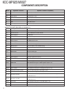
● ELECTRIC UNIT (X34-3030-10, X34-3032-71)
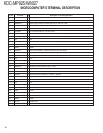
Ref No. Application / Functions Operation / Condition / Compatibility
IC1 System control IC System control microprocessor
IC2 E-VOL & tuner IC E-VOL. FM/AM tuner & stereo decoder
IC3 Power supply IC For A8V AVR
IC4 Audio power IC Audio power amplifier
IC5 System IC For System E’s control
IC6 Audio control IC For WOW/FOCUS control
IC7 Power supply IC -9V AVR (For 4.5V Pre-out)
IC8 Reset IC When BU5V line voltage is less than 3.5V, this IC output line is “L”
IC9 Muting logic IC Control for MUTE, P-ANT & RESET muting
IC10 Buffer IC For spectrum analyzer
IC11~13 OP AMP For 4.5V Pre-out
IC14 RDS decoder Decode for RDS signal
IC15,16 Motor driver Control for Panel mechanism motor
IC18 P-CON IC Power control IC
IC19 Power supply IC Switching regulator IC for CD4.7V
IC20 Analog SW Control for WOW/FOCUS IC (IC4)
Q1,2 BU 5V AVR While BU is applied when BU5V regulator output is +5V
Q3,601 SW5V AVR When Q601base level goes H, SW5V regulator output is +5V
Q4,5 SW14V AVR When Q5 base level goes H, SW14V regulator output is +14V
Q6~8 Audio 8V AVR When Q6 base level goes H, A8V regulator output is +8.3V
Q9,602 Servo +B AVR When Q602 base level goes H, S+B regulator output is +7.5V
Q11~14 Illumination & DC/DC +B AVR When Q11 base level goes H, AVR output is +9.2V
Q15,16 Audio 10.5V AVR When Q16 base level goes H, AVR output is +10.5V
Q17~19 Pre Amp & -9V AVR
Q18,19 work as differential amplifier, Q17 wark as driver and -9.1V is supplied to
OP AMP for Pre-out
Q20~22 Pre Amp & +9V AVR
Q20,22 work as differential amplifier, Q21 wark as driver and +9.4V is supplied to
OP AMP for Pre-out
Q23,24 P-ANT SW When Q23 base level goes H, P-ANT SW output is +14V
Q25 Buffer EX amp control buffer
Q26 Small lamp det. SW When Q26 base level goes H, Q26 turned ON
COMPONENTS DESCRIPTION


