


English
76
English
Power indicator
Power indicator
■
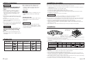
The protection function is activated in the following situations:
This unit incorporates a protection function which protects the main unit and speakers from
troubles. The unit stops to function when the protection function is activated.
•If the POWER INDICATOR lights in green:
• A speaker cable may be short-circuited.
• A speaker output may be in contact with the ground.
• The temperature of the internal parts may be higher than 120°C (248°F)
• The sigma servo connection may be erroneous.
• The fuse of this unit may be blown.
• The unit may be malfunctioning and sending DC signal to the speaker output.
•If the POWER INDICATOR does not light up:
• The grounding cable of this unit may not be connected with a metallic part which is
electrically connected with the negative terminal of the battery.
• The power control cable may not be connected to this unit.
• The grounding cable of the center unit (cassette receiver, CD receiver, etc.) may not be
connected with a metallic part which is electrically connected with the negative terminal of
the battery.
• The fuse of this unit may be blown.
■
Drop in supply voltage (If the POWER INDICATOR lights or blinks in
amber):
When the power supply voltage drops below 11.5 V, the POWER INDICATOR lights in amber.
If the POWER INDICATOR blinks or lights in amber, check the following items and make sure
to supply enough power to this unit.
• Is the battery cable too thin to supply enough power?
• Is the battery cable deteriorated?
• Is the battery exhausted?
Do not use thin or deteriorated cables for this may cause heat generation or burn. The cable
used should be thick enough (5 mm
2
or more) to supply power.
2CAUTION
■
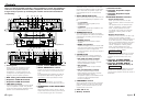
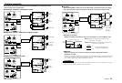
Power indicator:
This lamp indicates the status of the unit,
including the power supply and protection
function, by lighting in red, amber or green or
turning off.
When power is turned ON, it lights in green
for a few seconds, then turns red when
normal operation starts.
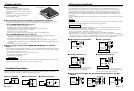
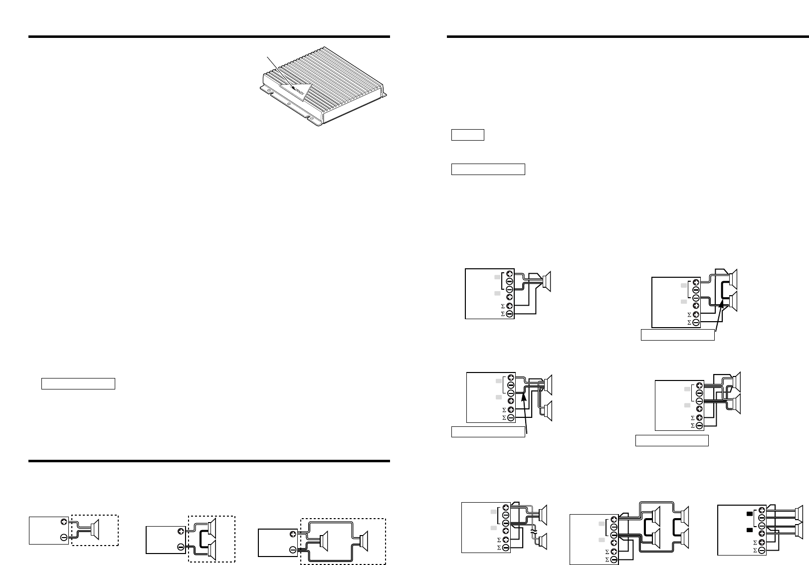
Combined Impedance
■
Basic connection
■
Series connection
■
Parallel connection
4 Ω
4 Ω
8 Ω
4 Ω
4 Ω
2 Ω
4 Ω 4 Ω
Refer to the diagrams below and ensure that the combined impedance is 2Ω or greater for
stereo connections and 4Ω or greater for bridged connections.
BRIDGED
Σ SERVO Ι
FEED BACK
L
R
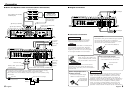
Sigma servo feed back
BRIDGED
Σ SERVO Ι
FEED BACK
L
R
The sound reproduced through conventional amplifiers is distorted due to the counterelectromotive
force produced in the oscillating system of the speaker. The counterelectromotive force is
particularly high with the woofer which requires a large drive mass.The sigma servo connection
reduces distortion caused by the counterelectromotive force by including the circuit up to the
speaker terminals in the negative feedback loop. This makes it possible to drive speakers with
more fidelity to the input signals and create a sharp bass sound image with few feeling of noise
interference.
The aforementioned effects will not be obtained when the sigma servo connection has not been
made.
The speaker cable and the sigma servo cable should be wired to run along the same route. Note
that this wiring should be separated from the power supply cable.
• The SIGMA SERVO FEEDBACK terminals should be connected properly. Failure to connect
them properly will be the cause of breakdown.
• The rated input of the speakers connected to this unit should be no less than the maximum
output of the amplifier. Otherwise malfunction may result.
Be specially careful in this when connecting speakers in a parallel configuration.
• Speakers that are to be used for bridged connections to this unit should have an impedance of
4Ω or greater. When connecting multiple speakers, ensure that the combined impedance is 4Ω
or greater. Connection of speakers of less than 4Ω will be the cause of breakdown.
2CAUTION
NOTE
BRIDGED
Σ SERVO Ι
FEED BACK
L
R
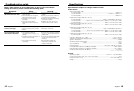
■
Basic sigma servo connection
■
Series connection
Make this cable as short as possible.
2CAUTION
■
Parallel connection (1)
The speaker cables connected to this unit
should be thick enough to supply the
current capacity of two speakers.
2CAUTION
This connection is possible only when the
speakers are identical and the speaker cables
are also of the same type and length.
2CAUTION
■
Stereo Connections When the Aforementioned Connections Are Not
Possible
■
Parallel connection (2)
BRIDGED
Σ SERVO Ι
FEED BACK
L
R
BRIDGED
Σ SERVO Ι
FEED BACK
L
R
Σ SERVO Ι
FEED BACK
BRIDGED
L
R
BRIDGED
Σ SERVO Ι
FEED BACK
L
R