


4
English English
5
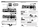
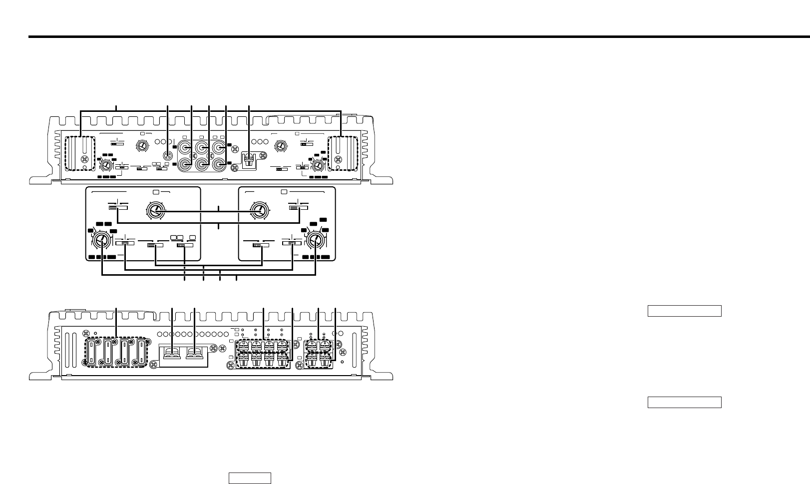
Controls
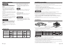
This is a 4 channel amplifier including 2 stereo amplifiers in a body. One amplifier is
referred to as amplifier A and the other is amplifier B. This unit is compatible with
a large variety of systems by combining the switches and functions described in
the following.
L
L
R
R
LINE IN
P.CON(REMOTE)
GND
MONO
LINE OUT
25Hz
15Hz
INFRASONIC
FILTER
OFF
OPERATION
MONOSTEREO
OPERATION
MONOSTEREO
25Hz
15Hz
INFRASONIC
OFF
LPF
OFF
HPF
FILTER
LPF
OFF
HPF
CONTROL
INPUT
SENSITIVITY(V)
0.25
0.5
1
2
FREQUENCY(Hz) FREQUENCY(Hz)
50
70
100
LPF 200
170
120
50
70
200
150
120100
HPF
150
3
4
INPUT
SELECTOR
LEFT
BRIDGED
SERVO Ι FEED BACK
RIGHT
SPEAKER OUTPUT
FUSE(20A×4)
BATT.
GND
BB
B
AA
B
B
B
A
A
A
A
A A
+
(MAX)
(MIN)
INPUT
SENSITIVITY(V)
0.25
0.5
1
2
3
4
(MAX)
(MIN)
CONTROL
B
50
70
100
LPF 200
170
120
50
70
200
150
120
100
HPF
150
Σ
20
20
20
20
25Hz
15Hz
INFRASONIC
FILTER
OFF
OPERATION
MONOSTEREO
LPF
OFF
HPF
CONTROL
INPUT
SENSITIVITY(V)
0.25
0.5
1
2
50
70
100
LPF 200
170
120
50
70
200
150
120100
HPF
150
3
4
INPUT
SELECTOR
B
A
A A
(MAX)
(MIN)
OPERATION
MONOSTEREO
25Hz
15Hz
INFRASONIC
OFF
FILTER
LPF
OFF
HPF
INPUT
SENSITIVITY(V)
0.25
0.5
1
2
3
4
(MAX)
(MIN)
CONTROL
B
50
70
100
LPF 200
170
120
50
70
200
150
120
100
HPF
150
1 2 3 4 5 6
7
# $ % ^ & * (
8
9
0 ! @
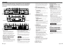
Amplifier A Amplifier B
1
Cooling fans
When the internal temperature of the
amplifier rises, the cooling fans are
activated automatically to drop the
temperature. In certain situations, the
cooling fans may be operating from the
beginning of the amplifier operation.
2
RCA cable ground lead terminal
3
Amplifier A LINE IN terminal
4
Amplifier B LINE IN terminal
5
LINE OUT terminal
These jacks output respectively the signals
input to amplifiers A and B. They always
output the stereo signals regardless of the
position of the OPERATION switch.
6
Power control (REMOTE) terminal
7
INPUT SENSITIVITY control
Adjust this control according to the pre-out
level of the center unit connected to this
amp.
The sensitivities of amplifiers A and B can
be adjusted independently regardless of
the position of the input selector switch.
Refer to “Specifications” on the center
unit’s instruction manual about the pre-out
level.
8
INFRASONIC FILTER FREQUENCY
switch
When this switch is set to 15 Hz or 25 Hz,
frequencies below the setting value will be
cut. This serves to get rid of unwanted
NOTE
vibrations that do not result in sound and
improves the speakers’ ability to reproduce
sound. Note that the speaker output will
automatically be set for monaural (L+R)
sound.
9
INPUT SELECTOR switch
This switch selects the input method of the
signals to be amplified by amplifiers A and
B.
• A B position:
Amplifies both of the signals input to
amplifiers A and B.
• A position:
Amplifies only signal input amplifier A with
both amplifiers A and B.
0
OPERATION switch
The amplification methods of the signals
input to amplifiers A and B can be selected
independently according to the setting of
this switch.
• STEREO position:
The amplifier can be used as a stereo
amplifier.
• MONO (Lch) position:
Amplifies the signal input from the left side
only. Set to this position and make bridged
connections to use as a high-power
monaural amplifier. (The input right signal is
not output.)
!
FILTER switch
This switch allows to apply high-pass or
low-pass filtering to the speaker outputs.
• HPF (High-Pass Filter) position:
The filter outputs the band of higher
frequencies than the frequency set with
the HPF FREQUENCY control.
• OFF position:
The entire bandwidth is output without
filtering.
• LPF (Low-Pass Filter) position:
The filter outputs the band of lower
frequencies than the frequency set with
the LPF FREQUENCY control.
The speaker output is automatically turned
monaural (L+R) and the bass boost
function is activated.
@
FREQUENCY control
When the FILTER switch is set to the HPF
(High-Pass Filter) or LPF (Low-Pass Filter)
position, the threshold frequency can be
adjusted with this control.
#
Fuse (20 A
×
4)
$
Battery terminal
%
Ground terminal
^
Amplifier A speaker output
terminals
&
Amplifier B speaker output
terminals
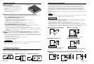
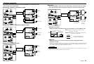
❖
SPEAKER OUTPUT terminals
• Stereo Connections:
When you wish to use the unit as a
stereo amplifier, stereo connections are
used.
The speakers to be connected should
have an impedance of 2Ω or greater.
When multiple speakers are to be
connected, ensure that the combined
impedance is 2Ω or greater for each
channel.
• Bridged Connections:
When you wish to use the unit as a high-
output monaural amplifier, bridged
connections are used. (Make connections
to the LEFT channel (+) and the RIGHT
channel (-) SPEAKER OUTPUT terminals.)
The speakers to be connected should
have an impedance of 4Ω or greater.
When multiple speakers are to be
connected, ensure that the combined
impedance is 4Ω or greater.
The rated input of the speakers should be
no less than the maximum output of the
amplifier. Otherwise malfunction may
result.
*
Amplifier A SIGMA SERVO
I
FEED BACK terminals (See p.7)
(
Amplifier B SIGMA SERVO
I
FEED BACK terminals (See p.7)
The SIGMA SERVO FEEDBACK terminals
should be connected properly. Failure to
connect them properly will be the cause of
breakdown.
2CAUTION
2CAUTION