


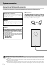
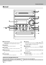
System connection
8
EN
DIGITAL
OUT
OPTICAL
AUX
INPUT
L
R
GND
AM
ANTENNA
FRONT
SPEAKERS
(6-16
Ω)
L
-
+
R
FM
75
Ω
DIGITAL
OUT
OPTICAL
GND
AM
ANTENNA
FM
75
Ω
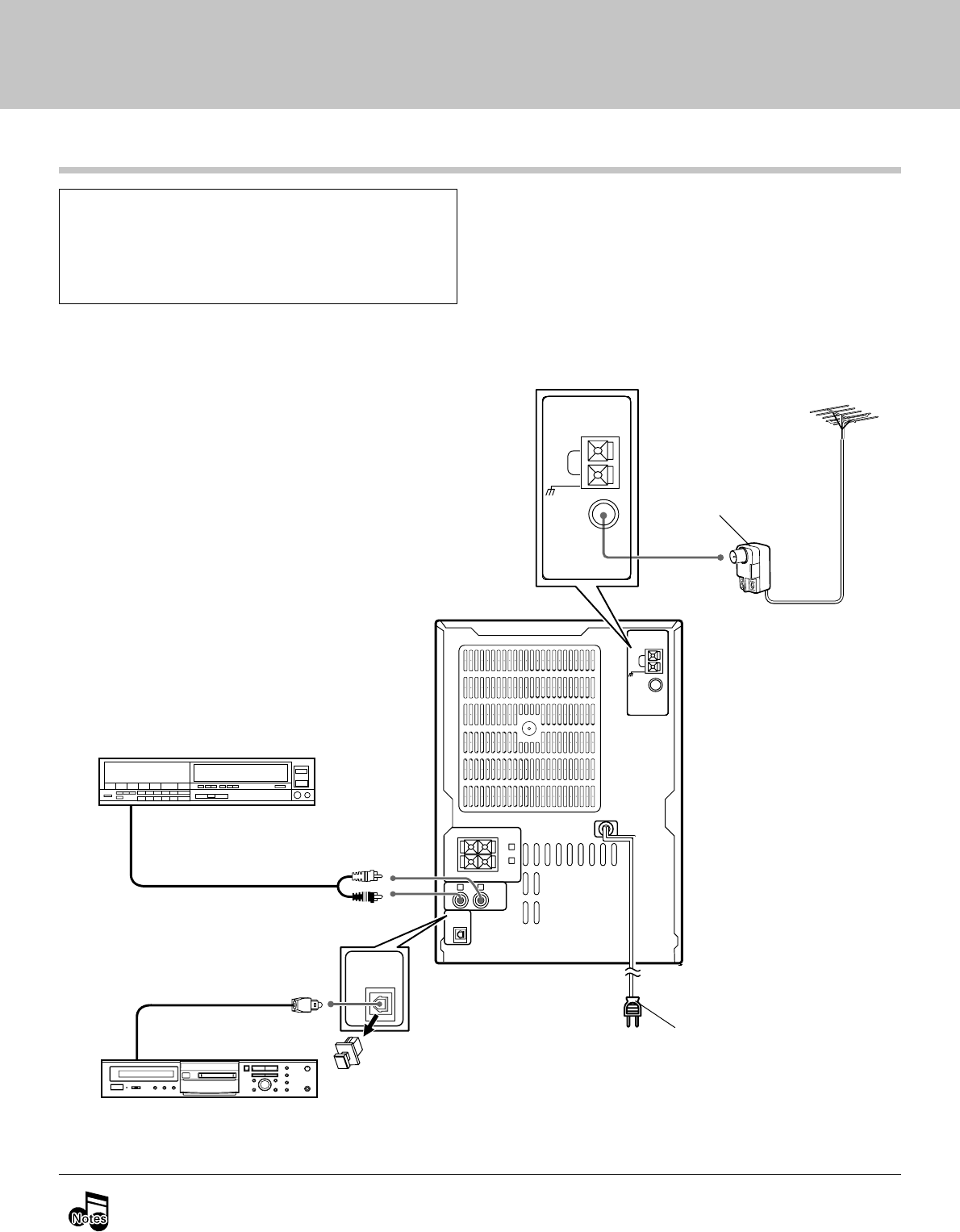
÷ In case an associated system component is connected, also read the instruction manual of the component.
÷ Be sure to insert all connection cords securely. If their connections are imperfect, the sound may not be
produced or noise may interfere.
÷ Before plugging or unplugging a connection cord, be sure to unplug the power cord from the wall AC outlet. If
connection cords are plugged or unplugged with the power cord left plugged in, malfunction or damage may result.
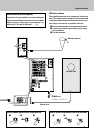
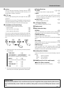
Connection of Other Accessories (Commercially Available Parts)
Lead the 75Ω coaxial cable connected to the FM out-
door antenna into the room and connect it to the
FM 75Ω terminal. Please remove the indoor an-
tenna after an outdoor antenna has been installed.
Connect the components as shown in the dia-
gram. Only plug the power cord into a power
outlet once connections are completed.
CAUTION
Note on Connection
Audio cord
Audio output
VCR, Analog turntable with built-in
RIAA equalizer (optional P-110), etc.
POWER cord
TO WALL AC OUTLET
Antenna adaptor
(Commercially
Available Parts)
FM outdoor antenna
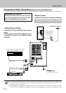
FM outdoor antenna
* DIGITAL OUT jack (OPTICAL)
cap
Optical fiber cable
The DIGITAL OUT jack (OPTICAL) outputs the CD
signal.
The CD signal can be recorded in digital format by
connecting a recorder to the DIGITAL IN jack
(OPTICAL).
MD recorder or DAT etc.
*
Digital input