


DVD DIGITAL THEATER SYSTEM
TH-A10
Simplified connection manual
Please see INSTRUCTIONS from page 6 to page 10 as well.
LVT0517-006A
Please see the reverse page.
J
V
C
0900TNMNATJSC
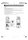
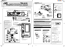
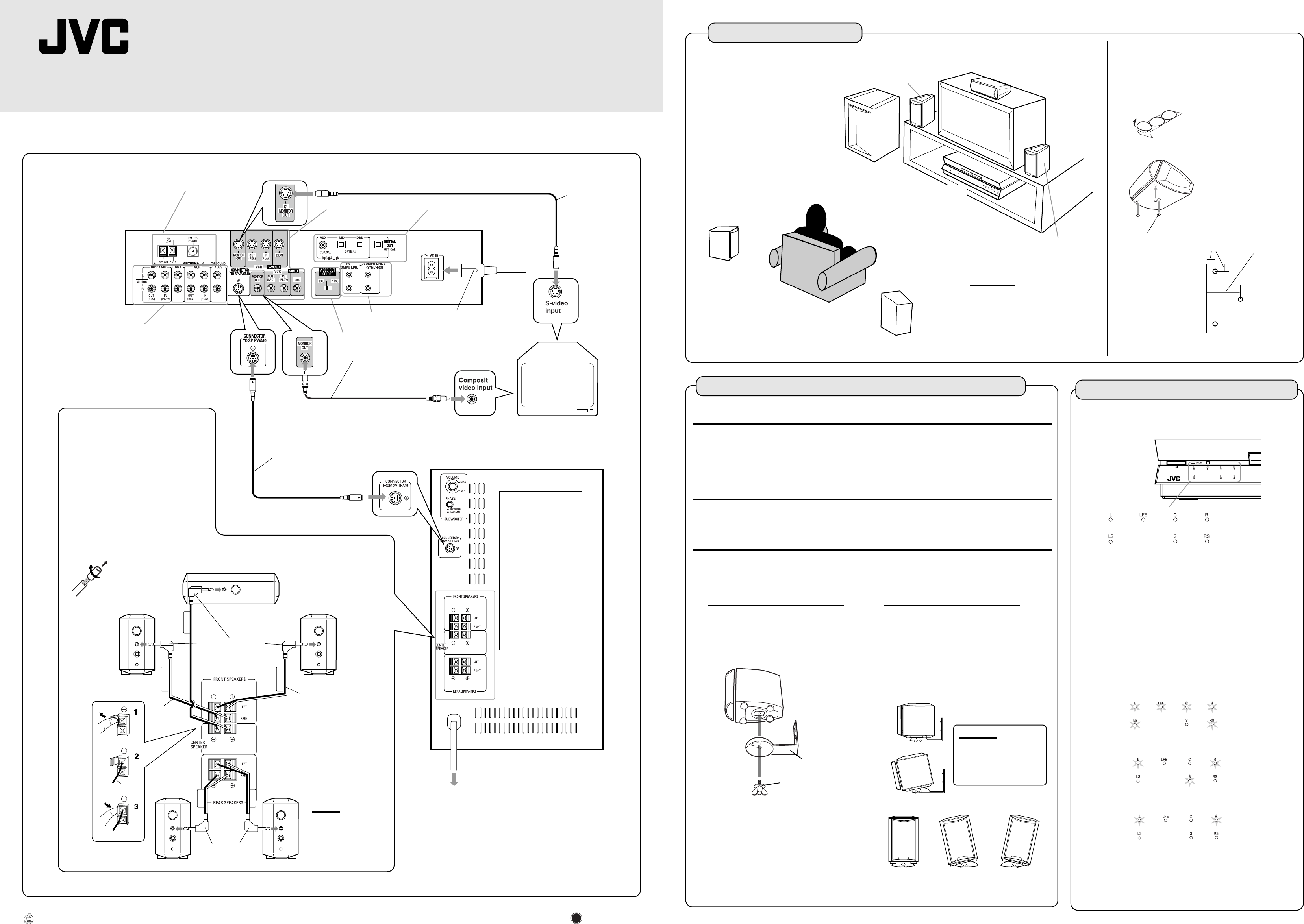
Installation
Example
TV
Satellite speaker
(front left stpeker)
Satellite speaker
(front right speaker)
Center speaker
Powered sub-woofer
Satellite speaker
(rear left speaker)
Satellite speaker
(rear right speaker)
The rear speakers are
placed behind the
listening position.
Center unit
CAUTIONS:
• For safety reasons, always ensure
that there is sufficient place behind
the powered sub-woofer.
• If the front and rear speakers are
placed on the floor, always ensure
that they are level.
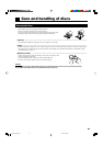
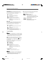
To attach non-slip rubbers to the center
speaker
Attach the supplied non-slip rubbers at three points on the
bottom of the center speaker.
1 cm (7/16”)
5 cm (2”)
Front side
Bottom
The non-slip rubbers are
adhesive. Peel off the seal
before applying.
Use the supplied bracket to fix satellite speakers to the wall.
CAUTION: ATTACHING THE BRACKETS ON THE WALL
When attaching the brackets on the wall, have them attached to the wall by a qualified
person.
DO NOT attach the brackets on the wall by yourself to avoid an unexpected damage of
their falling from the wall, caused by incorrect attachment or weakness in the wall.
Location of attachment to wall:
Care is required in selecting a location for attaching satellite speakers to the wall.
Injury to personnel, or damage to equipment, may result if the speakers are attached in a
location which interferes with daily activities.
Attaching speakers to the bracket
Tilting the speaker to the front
Tilting left-right
Bracket
CAUTION:
If the screw is not
tightened firmly, it may
cause injury to personnel
or damage to equipment.
Screw
1. Use the screw supplied to attach the
speaker to the bracket.
2. Adjusting the angle of the satellite
speakers
The angle of the speaker may be adjusted
in the front-rear and left-right directions
along the channel in the bracket.
When adjusting the angle, loosen the
screw slightly, make the adjustment, and
then tighten the screw firmly.
To hang satellite speakers from the wall
Attach non-slip rubbers at
the three points shown in the
diagram.
Attach two rubbers at left
and right at the front of the
speaker, and one in the
middle at the rear.
Non-slip rubber
English
EN, FR
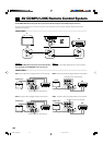
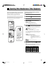
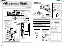
XV-THA10
(Center unit)
SP-PWA10 (Powered sub woofer)
FM and AM antenna terminals (6)
S-video output and
input terminals (6, 8, 9)
Digital input and
output terminals (9)
S-video cable
(not supplied)
Connect to the TV if
it has an S-video in-
put (for higher image
quality). Connect the
cables with the £
mark facing down.
AC power cord (supplied) (10)
Before plugging the center unit
into an AC outlet, make sure that
all connections have been made.
COMPU LINK
terminals (52, 54)
Video cable (supplied) (6)
Connect the MONITOR OUT
terminal to composit video
input terminal on the TV.
Yellow
Yellow
System cable (supplied) (6)
Connect the center unit to
powered sub woofer.
Ensure that the £
mark on the plug
faces to the right.
Ensure that
the £ mark
on the plug
faces upwards.
Analog audio input and output terminals (8, 9)
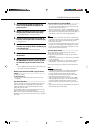
To connect speakers (7)
Connect the satellite speakers and center
speaker to the terminals on the powered
subwoofer using the speaker cords supplied.
Labels are attached to the speaker cords to
indicate the speaker and terminal to which
each is to be connected.
• The four satellite speakers may be used at
either front or rear.
• Ensure that the left and right speakers are
connected to left and right respectively, and
that they are connected with the correct
polarity (+ve, –ve). The white speaker cord
connects to the + terminal, and the black
speaker cord connects to the – terminal.
Twist and remove
the insulation at the
end of each speaker
cord.
Front right speaker
Front left speaker
Speaker cord (6 m)
(19.7 ft)
Center speaker
Rear left
speaker
Rear right
speaker
Speaker cord
(15 m) (49.2 ft)
White
Black
To AC outlet
Before plugging the powered sub woofer
into an AC outlet, make sure that all
connections have been made.
Note:
• Mixing up the polarity
of the speaker cords
can reduce the stereo
effect and sound
quality.
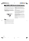
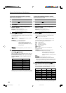
VIDEO OUT SELECT (7)
Uses lamps to display the audio channel configuration for the
disc currently playing.
The lamps refer to the speaker channel as follows.
L: Left front speaker channnel
R: Right front speaker channel
C: Center speaker channel
RS: Right surround speaker channel
LS: Left surround speaker channel
S: Rear speaker channel (monaural)
LFE: Sub woofer channel
The lamp display indicates the type of disc (DVD or CD)
currently playing as follows.
Example:
With Dolby Digital 5.1 ch, DTS Digital 5.1 ch, or MPEG
Multichannel 5.1 ch surround
With Dolby Digital (Lt/Rt)
With stereo sound (eg Audio CD)
Audio channel display lamp
• The audio channel
display lamp is not
an indicator of
which speakers are
producing sound.
When playing DVD recorded in Dolby Digital, Dolby Pro Logic,
DTS, or MPEG Multichannnel Surround Sound, set the main
system surround mode to “SURROUND ON.”
When it is set to “SURROUND OFF” the audio channel display
lamp will not change. However, sound will be played without
surround effects (see page 21).
SCM&4U 00.9.18, 8:57 PM1