


4
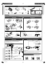
INSTALLATION / CONNECTION
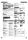
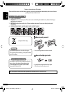
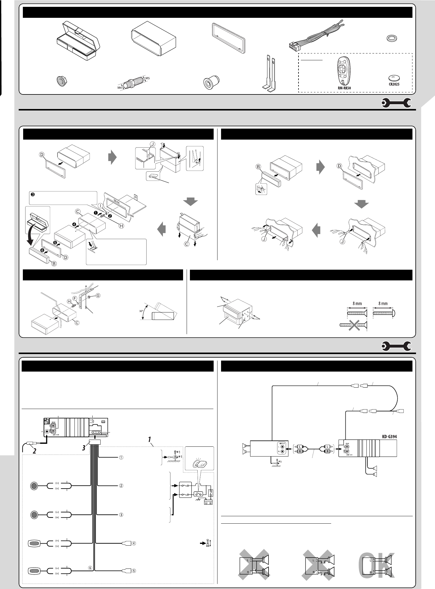
When using the optional stay
Install the unit at an angle of
less than 30˚.
Screw (option)
Stay (option)
Fire wall
Dashboard
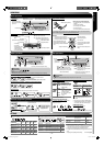
* Not supplied for this unit.
Flat type screws (M5 × 8 mm)*
Pocket
Flat type screws (M5 × 8 mm)*
Bracket*
Bracket*
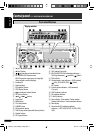
Removing the unit
In dash-mounting
Before removing the unit, release the rear section.
When installing the unit without using the sleeve
In a Toyota car for example, first remove the car radio and install the unit in its place.
Do the required electrical
connections.
Bend the appropriate tabs
to hold the sleeve firmly
in place.
When you stand the unit,
be careful not to damage
the fuse on the rear.
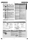
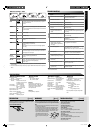
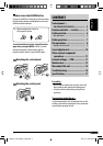
Purple
Front speaker (left)
To the remote lead of other equipment
(200 mA max.)—only for KD-G394
Blue
Red
To an accessory terminal in
the fuse block
To a live terminal in the
fuse block connecting to
the car battery (bypassing
the ignition switch)
(constant 12 V)
Yellow *
2
To the metallic body
or chassis of the car
Black
Ignition switch
*
1
Not supplied for this unit.
*
2
Before checking the operation of this unit prior to installation, this lead must be connected, otherwise the power cannot be
turned on.
*
3
Firmly attach the ground wire to the metallic body or to the chassis of the car—to the place uncoated with paint (if coated
with paint, remove the paint before attaching the wire). Failure to do so may cause damage to the unit.
15 A fuse
Fuse block
Rear speaker (left)
Rear speaker (right)
Front speaker (right)
White with black stripe
Line out (only for KD-G394)
Rear ground terminal
Antenna
terminal
Rear
speakers
Remote lead
Remote lead (blue with white stripe)
To the remote lead of other equipment
or automatic antenna if any
Y-connector *
1
Gray with black stripe
Green
Gray
Green with black stripe
Purple with black stripe
White
JVC Amplifier
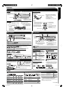
ELECTRICAL CONNECTIONS
Typical connections Connecting the external amplifier (for KD-G394)
INSTALLATION
The following illustration shows a typical installation. If you have any questions or require information regarding installation kits, consult your JVC car audio dealer or a company supplying kits.
• If you are not sure how to install this unit correctly, have it installed by a qualified technician.
Connect only the front speakers if your
speaker system is two-speaker system.
PRECAUTIONS on power supply and speaker connections:
• DO NOT connect the speaker leads of the power cord to the car battery; otherwise, the unit will be
seriously damaged.
• BEFORE connecting the speaker leads of the power cord to the speakers, check the speaker wiring in your car.
Before connecting: Check the wiring in the vehicle carefully. Incorrect connection may cause serious damage to this
unit. The leads of the power cord and those of the connector from the car body may be different in color.
1 Connect the colored leads of the power cord in the order specified in the illustration below.
2 Connect the antenna cord.
3 Finally connect the wiring harness to the unit.
Signal cord *
1
Front speakers
To the automatic antenna if any
(250 mA max.)
Blue with white
stripe
For KD-G394
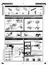
J
Handles
F
Washer (ø5)
G
Lock nut (M5)
H
Mounting bolt
(M4 × 5 mm;
M5 × 15 mm)
I
Rubber cushion
C
Sleeve
D
Trim plate
E
Power cord
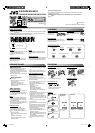
Parts list for installation and connection
A/B
Hard case (for
KD-G394)/
Control panel
K
Remote controller
L
Battery
For KD-G394
EN_KD-G394[UI]f.indd 4EN_KD-G394[UI]f.indd 4 9/12/07 5:24:27 PM9/12/07 5:24:27 PM