


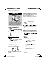
KW-XC404
Installation/Connection Manual
GET0328-002A
[UI]
0805DTSMDTJEIN
EN
• This unit is designed to operate on 12 V DC, NEGATIVE ground electrical systems. If your
vehicle does not have this system, a voltage inverter is required, which can be purchased at
JVC car audio dealers.
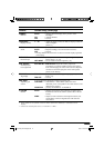
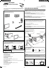
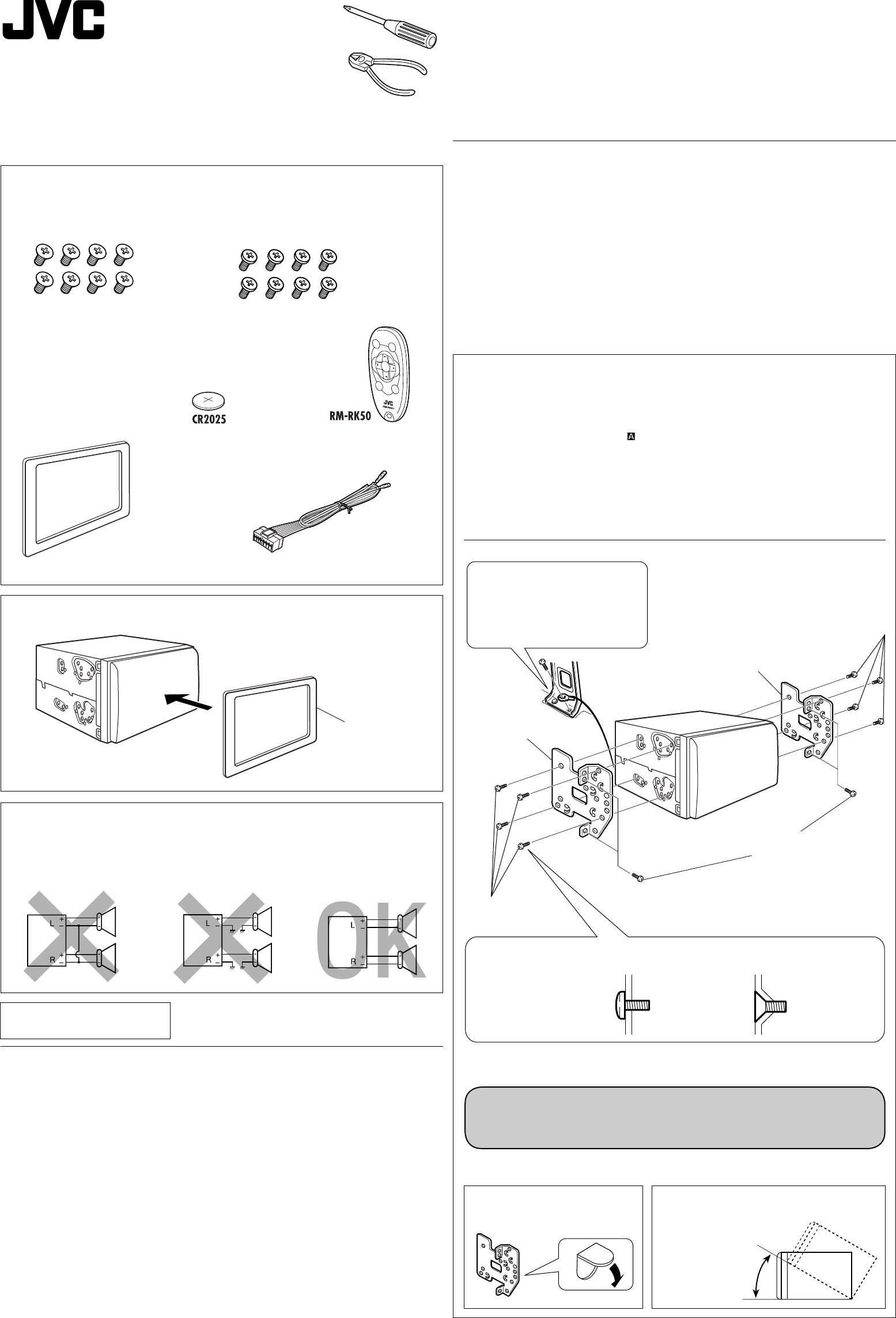
Parts list for installation and connection
The following parts are provided for this unit.
After checking them, please set them correctly.
INSTALLATION (IN-DASH MOUNTING)
The following illustration shows a typical installation. However, you should make adjustments
corresponding to your specific car. In this case consult the manual included with the installation
kit (option).
In some case, depending of the type and the model of your car, it is not possible to install the
unit into the center console.
If you have any questions or require information regarding installation kits, consult your
JVC car audio dealer or a company supplying kits.
• If you are not sure how to install this unit correctly, have it installed by a qualified technician.
Before installing the unit
• When mounting the unit, be sure to use the screws provided, as instructed. If other screws are
used, there is a possibility that parts could become loose or damaged.
• When tightening screws or bolts be careful not to pinch any connection cord.
TROUBLESHOOTING
• The fuse blows.
* Are the red and black leads connected correctly?
• Power cannot be turned on.
* Is the yellow lead connected?
• No sound from the speakers.
* Is the speaker output lead short-circuited?
• Sound is distorted.
* Is the speaker output lead grounded?
* Are the “–” terminals of L and R speakers grounded in common?
• Noise interfere with sounds.
* Is the rear ground terminal connected to the car’s chassis using shorter and thicker cords?
• Unit becomes hot.
* Is the speaker output lead grounded?
* Are the “–” terminals of L and R speakers grounded in common?
• This unit does not work at all.
* Have you reset your unit?
1
Battery
Remote controller
Binding screws
(M5 x 8 mm)
Power cord
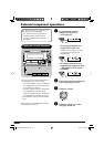
1 Remove the audio system originally installed together with the mounting brackets.
Note: Be sure to keep all the screws and parts removed from your car for future use.
2 Attach the mounting brackets (removed from the car), to this unit (see below).
3 Connect the wires (see diagram ).
4 Fix this unit to the car using the screws removed in step 1.
• See “Caution” below.
The following example shown is for installation in a Toyota. For more details, consult
your JVC car audio dealer.
Securely connect the ground wire to
the metal body of the car using the
screw originally fixed to the metal
body of the car.
Mounting bracket
removed from the car
Screws supplied
for this unit
Screw removed from the car in step 1
Install the unit at an angle of less than 30°.
Less than 30˚
If there is an interfering tab on the
mounting bracket, bent it flat.
© 2005 Victor Company of Japan, Limited
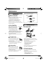
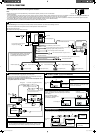
Caution:
To install the mounting brackets to the unit, use only the supplied screws (M5 x 8 mm).
If you use any screw longer than 8 mm, the unit can be damaged.
PRECAUTIONS on power supply and speaker connections:
• DO NOT connect the speaker leads of the power cord to the car battery; otherwise,
the receiver will be seriously damaged.
• BEFORE connecting the speaker leads of the power cord to the speakers, check the
speaker wiring in your car.
When installating the unit in a Nissan car
Fix the supplied plate as illustrated.
Plate for use with a
Nissan car
Plate for use with a Nissan car
Flat countersunk screws
(M5 x 8 mm)
Screws supplied for this unit:
Binding screws
(M5 x 8 mm)
Flat countersunk
screws (M5 x 8 mm)
Mounting bracket
removed from the car
Screws supplied for this unit
Select the proper screw
type, fitting to your car.
Instal1_KW-XC404[UI]f.indd 1Instal1_KW-XC404[UI]f.indd 1 8/3/05 6:25:34 PM8/3/05 6:25:34 PM