


3
*
2
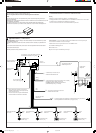
Before checking the operation of this unit prior to
installation, this lead must be connected, otherwise
power cannot be turned on.
*
2
Sebelum memeriksa pengoperasian unit ini sebelum
pemasangan, ujung kabel ini harus tersambung
terlebih dahulu, jika tidak power tidak akan dapat
dinyalakan.
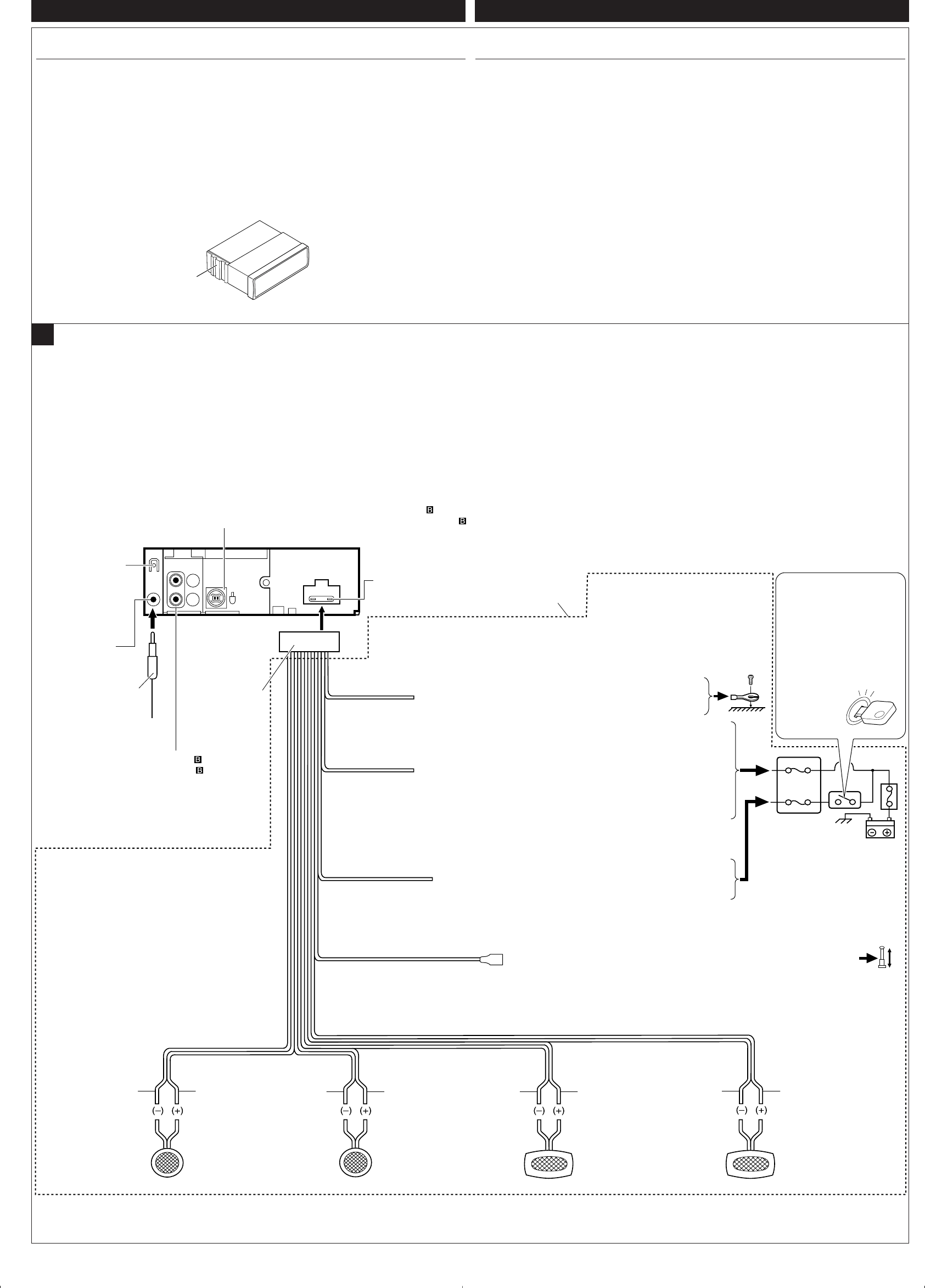
15 A fuse
Sekering 15 A
Yellow*
2
Kuning
*
2
Blue with white stripe
Biru dengan garis putih
Red
Merah
Fuse block
Kotak sekering
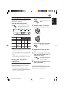
To a live terminal in the fuse block connecting to the car battery
(bypassing the ignition switch) (constant 12 V)
Ke terminal live pada kotak sekering yang tersambung ke baterai mobil
(melewati sakelar semula) (12 V konstan)
To metallic body or chassis of the car
Ke bagian logam atau rangka kendaraan
*
1
Not included with this unit
*
1
Tidak terdapat pada unit ini
Black
Hitam
To an accessory terminal in the fuse block
Ke terminal aksesoris pada kotak sekering
Gray with black stripe
Kelabu dengan garis
hitam
White
Putih
White with black stripe
Putih dengan garis hitam
Green with black stripe
Hijau dengan garis hitam
Gray
Kelabu
Green
Hijau
Purple with black stripe
Ungu dengan garis
hitam
Purple
Ungu
Rear ground terminal
Terminal ground
belakang
To the remote lead of other equipment or automatic antenna if any (200 mA max.)
Untuk pengarah remote dari peralatan yang lain atau antena otomatis jika ada
(maksimum 200 mA)
Line out (see diagram )
Line out (lihat diagram )
A
Left speaker (rear)
Speaker kiri (belakang)
Right speaker (front)
Speaker kanan (depan)
Left speaker (front)
Speaker kiri (depan)
Right speaker (rear)
Speaker kanan (belakang)
Ignition switch
Kunci starter
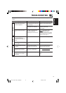
Typical Connections/Penyambungan Khusus
Antenna terminal
Terminal antena
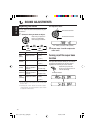
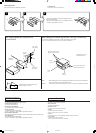
ELECTRICAL CONNECTIONS
To prevent short circuits, we recommend that you disconnect the battery’s negative terminal and
make all electrical connections before installing the unit.
• Be sure to ground this unit to the car’s chassis again after installation.
Notes:
• Replace the fuse with one of the specified rating. If the fuse blows frequently, consult your
JVC car audio dealer.
• Maximum input of the speakers should be more than 45 W at the rear and 45 W at the front, with
an impedance of 4 Ω to 8 Ω.
• To prevent short-circuit, cover the terminals of the UNUSED leads with insulating tape.
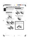
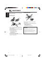
• The heat sink becomes very hot after use. Be careful not to touch it when removing this unit.
Heat sink
Penyerap panas
ENGLISH
Before connecting: Check the wiring in the vehicle carefully. Incorrect connection may cause
serious damage to this unit.
The leads of the power cord and those of the connector from the car body may be different in
color.
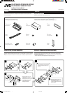
1
Connect the colored leads of the power cord in the order specified in the illustration below.
2
Connect the antenna cord.
3
Finally connect the wiring harness to the unit.
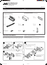
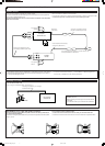
To CD Changer—only for KS-FX385/KS-FX385S/KS-FX385G (see diagram )
Untuk CD changer—hanya untuk KS-FX385/KS-FX385S/KS-FX385G (lihat diagram )
INDONESIA
1
2
*
1
*
1
1
2
3
4
5
3
15
PENYAMBUNGAN LISTRIK
Untuk mencegah terjadinya korsleting, sangat dianjurkan apabila anda mencabut terminal baterai
negatif dan memasang semua sambungan listrik sebelum memasang unit.
• Yakinkan kembali ground dari unit ini apakah sudah terpasang atau belum setelah
instalasi selesai.
Catatan:
•
Ganti sekering dengan sekering lain yang sesuai dengan syarat spesifikasi. Jika sekering sering
terbakar, tanyakan pada dealer audio mobil JVC.
•
Input maksimum speaker sebaiknya lebih dari 45 W pada bagian belakang dan 45 W pada
bagian depan dengan impedansi antara
4
Ω sampai 8
Ω
.
•
Untuk mencegah terjadinya korsleting, tutup ujung kabel yang tidak TERPAKAI dengan pita
insulator.
•
Penyerap panas akan menjadi sangat panas setelah pemakaian. Berhati-hatilah untuk tidak
menyentuhnya saat memindahkan unit ini.
Sebelum menghubungkan listrik:
Periksa kabel-kabel dalam peralatan anda dengan hati-hati.
Hubungan yang salah dapat menyebabkan kerusakan serius pada unit ini.
Kabel dalam kabel listrik dan juga konektor kendaraan memiliki warna yang berlainan.
1 Hubungkan petunjuk warna pada kabel power dalam urutan yang ditunjukkan pada ilustrasi di
bawah.
2 Sambungkan kabel antena.
3 Sambungkan sarung kabel dengan unit.
Instal3-4_KS-FX385_185[UN]f.p65 21/5/04, 5:49 PM3