


3
*
2
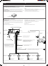
Before checking the operation of this unit prior to
installation, this lead must be connected, otherwise
power cannot be turned on.
*
2
°ËÕπ°“√µ√«®Õ∫°“√∑”ß“π¢Õß™ÿ¥ª√–°Õ∫π’È°ËÕπ∑’Ë®–µ‘¥µ—Èß
µÈÕßµËÕ“¬µ–°—Ë«π’È°ËÕπ ¡‘©–π—Èπ®–‰¡Ë“¡“√∂‡ª‘¥‡§√◊ËÕ߉¥
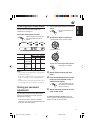
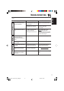
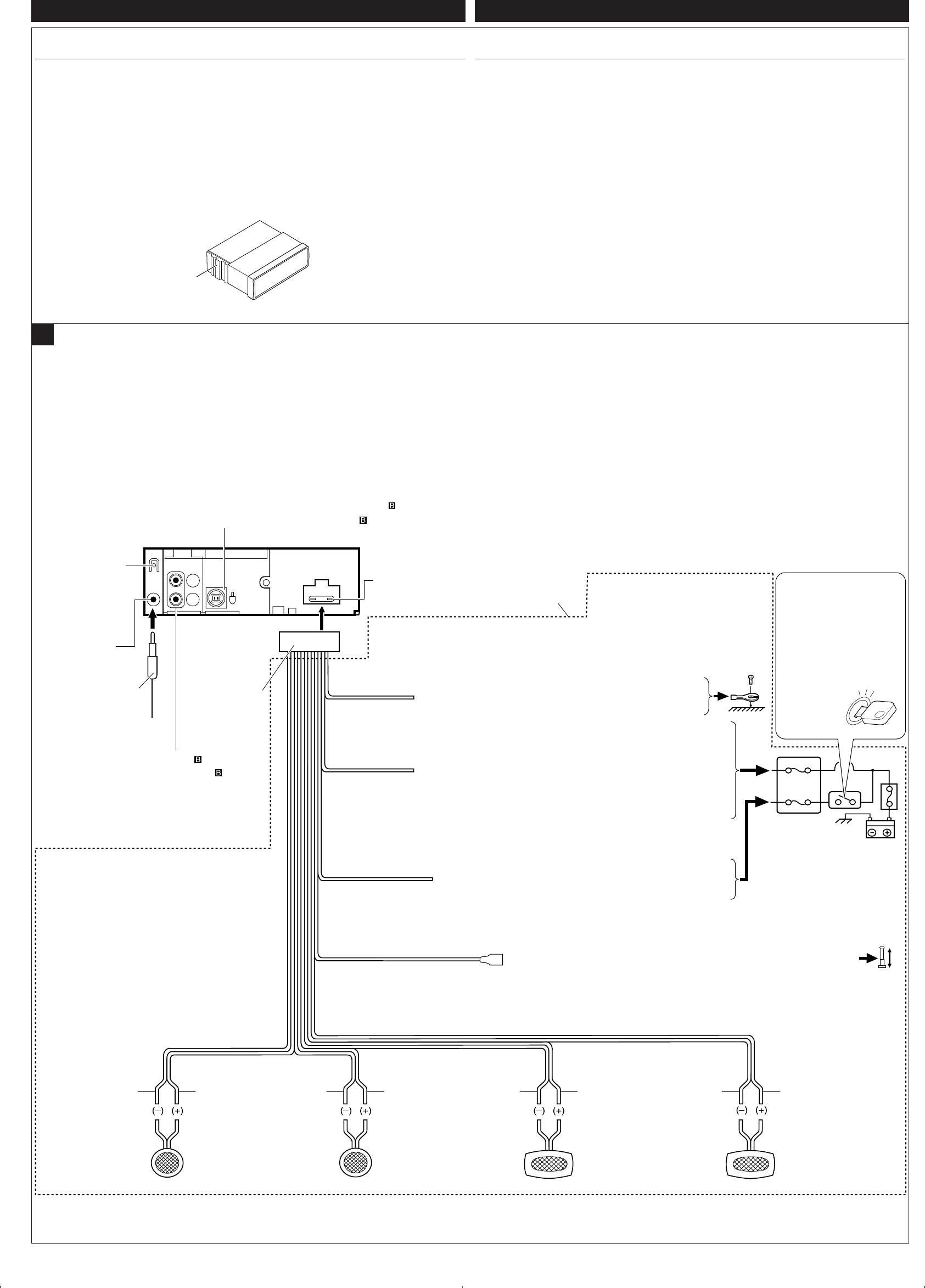
15 A fuse
ø‘«Ï¢π“¥ 15 A
Yellow*
2
’‡À≈◊Õß*
2
Blue with white stripe
’πÈ”‡ß‘π≈“¬¢“«
Red
’·¥ß
Fuse block
·ºßø‘«
To a live terminal in the fuse block connecting to the car battery
(bypassing the ignition switch) (constant 12 V)
µËÕ°—∫¢—È«∑’Ë¡’°√–·‰øøÈ“„π·ºßø‘«Ï ´÷ËßµËÕ°—∫·∫µ‡µÕ√’Ë√∂¬πµ
(‚¥¬‰¡ËµÈÕß„™È«‘∑™Ï®ÿ¥√–‡∫‘¥) (12 ‚«≈∑ϧß∑’Ë)
To metallic body or chassis of the car
µËÕ°—∫‚§√ß‚≈À–À√◊Õ‡™´‘¢Õß√∂¬πµÏ
*
1
Not included with this unit
*
1
‰¡Ë‰¥È„ÀÈ¡“°—∫™ÿ¥ª√–°Õ∫π
Black
’¥”
To an accessory terminal in the fuse block
µËÕ°—∫¢—È«Ë«πª√–°Õ∫„π·ºßø‘«
Gray with black stripe
’‡∑“·∂∫¥”
White
’¢“«
White with black stripe
’¢“«·∂∫¥”
Green with black stripe
’‡¢’¬«·∂∫¥”
Gray
’‡∑“
Green
’‡¢’¬«
Purple with black stripe
’¡Ë«ß·∂∫¥”
Purple
’¡Ë«ß
Rear ground terminal
®ÿ¥‡™◊ËÕ¡µËÕ“¬¥‘π¥È“πÀ≈—ß
To the remote lead of other equipment or automatic antenna if any (200 mA max.)
µËÕ“¬°—∫Õÿª°√≥ÏÕ◊ËπÀ√◊Õ‡“Õ“°“»Õ—µ‚π¡—µ‘∂È“¡’ (¢π“¥Ÿßÿ¥ 200 mA)
Line out (see diagram )
“¬ÕÕ° (Line out) (¥Ÿ·ºπ¿Ÿ¡ )
A
Left speaker (rear)
≈”‚æß´È“¬ (À≈—ß)
Right speaker (front)
≈”‚æߢ«“ (ÀπÈ“)
Left speaker (front)
≈”‚æß´È“¬ (ÀπÈ“)
Right speaker (rear)
≈”‚æߢ«“ (À≈—ß)
Ignition switch
«‘∑™Ï®ÿ¥√–‡∫‘¥
Typical Connections / °“√‡™◊ËÕ¡µËÕ·∫∫ª°µ‘
Antenna terminal
¢—È«“¬Õ“°“»
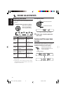
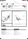
ELECTRICAL CONNECTIONS
To prevent short circuits, we recommend that you disconnect the battery’s negative terminal and
make all electrical connections before installing the unit.
• Be sure to ground this unit to the car’s chassis again after installation.
Notes:
• Replace the fuse with one of the specified rating. If the fuse blows frequently, consult your
JVC car audio dealer.
• Maximum input of the speakers should be more than 45 W at the rear and 45 W at the front, with
an impedance of 4 Ω to 8 Ω.
• To prevent short-circuit, cover the terminals of the UNUSED leads with insulating tape.
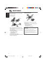
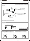
• The heat sink becomes very hot after use. Be careful not to touch it when removing this unit.
ENGLISH
Before connecting: Check the wiring in the vehicle carefully. Incorrect connection may cause
serious damage to this unit.
The leads of the power cord and those of the connector from the car body may be different in
color.
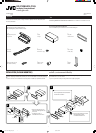
1
Connect the colored leads of the power cord in the order specified in the illustration below.
2
Connect the antenna cord.
3
Finally connect the wiring harness to the unit.
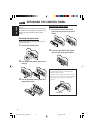
To CD Changer—only for KS-FX385 (see diagram )
‡¢È“‡§√◊ËÕ߇≈Ëπ´’¥’—KS-FX385 ‡∑Ë“π—Èπ (¥Ÿ·ºπ¿Ÿ¡ )
‰∑¬
1
2
*
1
*
1
1
2
3
4
5
3
15
°“√‡™◊ËÕ¡‚¥¬„™È ‰øøÈ“
‡æ◊ËÕªÈÕß°—π°“√‡°‘¥‰øøÈ“≈—¥«ß®√¢Õ·π–π”„ÀȪ≈¥¢—È«·∫µ‡µÕ√’Ë≈∫ÕÕ° ·≈È«®÷ßµËÕ“¬‰ø°ËÕ𵑥µ—È߇§√◊ËÕß
• µ√«®Õ∫„ÀÈ·πË „®«Ë“‰¥È‡¥‘𓬥‘πµËÕ√–À«Ë“߇§√◊ËÕß°—∫µ—«∂—ß √∂¬πµÏ„À¡Ë·≈È«À≈—ß®“°µ‘¥µ—Èß
À¡“¬‡Àµÿ:
• „™Èæ‘°—¥®”‡æ“–·∑πø‘« À“°ø‘«Ï¢“¥∫ËÕ¬ „ÀȪ√÷°…“√È“ π¢“¬‡§√◊ËÕ߇’¬ß√∂¬πµÏ JVC
•
·√ߢ—∫Ÿßÿ¥‡¢È“≈”‚æ߉¡Ë§«√‡°‘π°«Ë“ 45 W ∑’Ë≈”‚æßÀ≈—ß ·≈– 45 W ∑’Ë≈”‚æßÀπÈ“ ‚¥¬¡’§«“¡µÈ“π∑“π 4 Ω ∂÷ß 8 Ω
• °“√ªÈÕß°—π°“√≈—¥«ß®√ ®–µÈÕßæ—π¢—È«“¬µ–°—Ë« ∑’ˉ¡Ë„™È·≈È«¥È«¬‡∑ ªæ—𓬉ø
• ·ºËπ√–∫“¬§«“¡√ÈÕπ®–√ÈÕπ¡“°À≈—ß®“°„™È √–¡—¥√–«—ßլ˓‰ª —¡º—‡¡◊ËÕ∂Õ¥™ÿ¥ª√–°Õ∫π’È
Heat sink
·ºËπ√–∫“¬§«“¡√ÈÕπ
°ËÕ•∑”°“•‡™•ËÕ¡µËÕ: µ•«®†Õ•°“•‡¥‘•†“¬‰ø„•••¬•µÏլ˓ߕ–¡—¥•–«—լ˓„ÀȺ‘¥æ•“¥„•°“•‡™•ËÕ¡µËÕ™ÿ¥ª•–°Õ•™ÿ¥•’
°“•‡™•ËÕ¡µËÕº‘¥æ•“¥Õ“®∑”„Àȇ°‘¥§«“¡‡†’¬À“¬•È“¬·•ß°—•™ÿ¥ª•–
°Õ••’ȉ¥È“•µ–°—Ë«¢Õ߆“¬‰ø ·•–¢ÕßÕÿª°••ÏµËÕ‡™•ËÕ¡®“°µ—«• ß••Õ“®¡’†’∑’ˉ¡Ë‡À¡•Õ•°—•
1
µËÕ“¬‰ø’µ“¡≈”¥—∫∑’Ë√–∫ÿ„π√Ÿª¥È“π≈Ë“ß
2
‡™◊ËÕ¡µËÕ°—∫“¬Õ“°“»
3
ÿ¥∑È“¬ µËÕË«π§«∫§ÿ¡°“√‡¥‘𓬉ø‡¢È“°—∫™ÿ¥ª√–°Õ∫™ÿ¥π’È
Instal3-4_KS-FX385[U_UH]f.p65 5/19/04, 8:44 AM3