


2
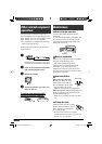
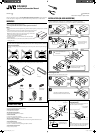
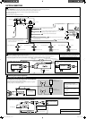
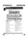
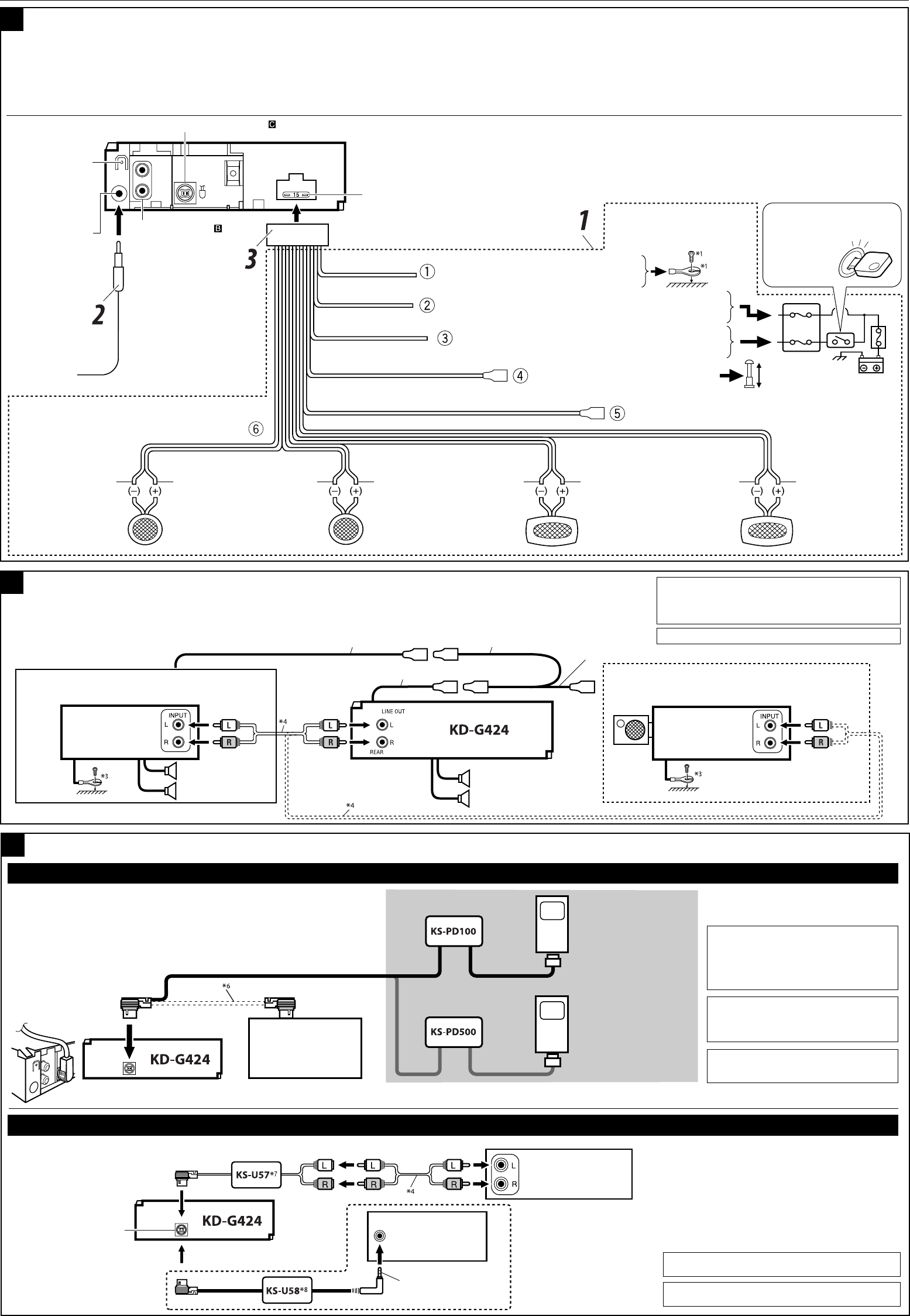
Typical connections
Before connecting: Check the wiring in the vehicle carefully. Incorrect connection may cause serious damage to this unit.
The leads of the power cord and those of the connector from the car body may be different in color.
1 Connect the colored leads of the power cord in the order specified in the illustration below.
2 Connect the antenna cord.
3 Finally connect the wiring harness to the unit.
PurplePurple with black stripeGreenGreen with black stripeGrayGray with black stripeWhite
White with black stripe
A
ELECTRICAL CONNECTIONS
To the automatic antenna if any (250 mA max.)
To the remote lead of other equipment (200 mA max.)
To metallic body or chassis of the car
To a live terminal in the fuse block connecting to the car battery
(bypassing the ignition switch) (constant 12 V)
To an accessory terminal in the fuse block
Right speaker (rear)Left speaker (rear)
Right speaker (front)Left speaker (front)
*
2
Before checking the operation of this unit prior to
installation, this lead must be connected, otherwise
power cannot be turned on.
15 A fuse
Line out (see diagram
)
Antenna terminal
Rear ground
*
1
Not supplied for this unit.
Ignition switch
Fuse block
Black
Blue with white stripe
Red
Yellow
*
2
Blue
To external components (see diagram )
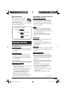
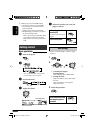
Connecting the external amplifier or subwoofer
You can connect an amplifier to upgrade your car stereo system.
• Connect the remote lead (blue with white stripe) to the remote lead of the other equipment so that it can be controlled through this unit.
• Disconnect the speakers from this unit, connect them to the amplifier. Leave the speaker leads of this unit unused.
B
Remote lead
Remote lead (Blue with white stripe)
To the remote lead of other equipment or automatic antenna if any
Y-connector (not supplied for this unit)
Rear speakers
Set “L/O MODE” to “REAR” (See page 13 of the INSTRUCTIONS.)
You can connect a power amplifier for rear speakers.
JVC Amplifier
Subwoofer
Set “L/O MODE” to “WOOFER” (See page 13 of the INSTRUCTIONS.)
You can also connect a subwoofer to the REAR LINE OUT
terminals.
JVC Amplifier
Front speakers
*
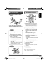
3
Firmly attach the ground wire to the metallic body or to
the chassis of the car—to the place uncoated with paint (if
coated with paint, remove the paint before attaching the
wire). Failure to do so may cause damage to the unit.
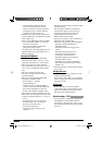
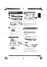
Other external component
• Set “EXT IN” for the external input setting (See page 13 of the INSTRUCTIONS.)
CAUTION :
• Before connecting the external
components, make sure that the unit is
turned off.
External component
3.5 mm stereo mini plug
CD changer jack
CD changer, Apple iPod®, or JVC D. player
You can connect these components as illustrated below.
The iPod*
5
or D. player can be connected using an interface adapter (not supplied)—
KS-PD100 (for iPod) or KS-PD500 (for D. player).
*
6
Connecting cord supplied for your CD
changer
Connecting the external components
C
• Set “CHANGER” for the external input setting (See page 13 of the INSTRUCTIONS.)
Apple iPod
(separately purchased)
JVC D. player
(separately purchased)
JVC CD changer
*
5
iPod is a trademark of Apple Computer,
Inc., registered in the U.S. and other
countries.
*
7
Line Input Adapter KS-U57 (not supplied for this unit)
or
*
8
AUX Input Adapter KS-U58 (not supplied for this unit)
CD changer jack
External component
*
4
Signal cord (not supplied for this unit)
Instal1-2_KD-G424_002A_1.indd 2Instal1-2_KD-G424_002A_1.indd 2 11/28/05 2:11:02 PM11/28/05 2:11:02 PM