


ENGLISH
• This unit is designed to operate on 12 volts DC, NEGATIVE
ground electrical systems.
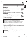
INSTALLATION (IN-DASH
MOUNTING)
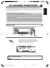
• The following illustration shows a typical installation. However,
you should make adjustments corresponding to your specific
car. If you have any questions or require information regarding
installation kits, consult your JVC car audio dealer or a company
supplying kits.
J
V
C
wÐdŽwÐdŽ
wÐdŽwÐdŽ
wÐdŽ
•
w?zU?Ðd?N? —U?O?ð W?D?Ý«u?Ð q?L?FO “UN'« «c¼ rLbI d?ýU³
DCÆVUÝ i¹—Qð WOzUÐdN WLE½« ¨Xu ±≤ ¨
ðð
ðð
ð
dd
dd
d
OO
OO
O
VV
VV
V
««
««
«
''
''
'
NN
NN
N
UU
UU
U
““
““
“
®®
®®
®
œœ
œœ
œ
««
««
«
šš
šš
š
qq
qq
q
‡‡
‡‡
‡
ðð
ðð
ð
UU
UU
U
ÐÐ
ÐÐ
Ð
KK
KK
K
uu
uu
u
««
««
«
OO
OO
O
UU
UU
U
——
——
—
……
……
…
©©
©©
©
•¹³OÒs «d?Ýr «²u{O×w «²U?w Þd¹IW «²dO?V «*¦UOWÆ l
–p?¨ ¹−?V?? ŽK?O?p? ŽL?q? ðF??b?¹ö? ðD?U?Ðo? ½u??Ÿ «?O?U?—… «²?w??
9²KJNUÆ «–« UÊ ¼MU„ «Ý²HU—« «Ë ŠUłW *FKuU ÐBu’
«œË« «²?d??O?V?¨ ¹d?łv?? «Ý²?A?U?—… u??“Ÿ «ôłN?e?… «B?u??ðO?W?
KOU—« U—W JVC «Ë «AdW «*u“ŽW Nc… «ôœË«Æ
0101HISFLEJES
EN, CH, AR
GET0020-002A
[U]
±
³³
³³
³
qq
qq
q
««
««
«
²²
²²
²
dd
dd
d
OO
OO
O
VV
VV
V
∫∫
∫∫
∫ «{Gj «e—
®“— %d¹d uŠW «²×Jr©
HBq uŠW «²×Jr «–« U½X uuW ÝUÐIUÆ
*
ŽMb «A×s s «*BMl¨ - Ë{l uŠW «²×Jr œ«šq «BMbË‚Æ
≤≤
≤≤
≤«½eŸ uŠW «e¹MWÆ
≥≥
≥≥
≥«½eŸ «NOJq «u«w ÐFb Bq ¦³²U «NOJq «u«wÆ
±«Ën «'NU“ ÐAJq ŽLuœÍÆ
öö
öö
ö
ŠŠ
ŠŠ
Š
E?E?
E?E?
E?
WW
WW
W
∫∫
∫∫
∫ ŽM?b ðu?On «'N?U“¨ ðQ?b s Žb? ðCd?— «Ë
«ðö· «HOu“ «*ułuœ w «'NW «)KHOW s «'NU“Æ
≤«œšq? «*U?²5? Ð5? «'NU?“ Ë«NO?Jq? «u?«w¨ L?U ¼u?
³5 w «AJq¨ HBq ¦³²U «NOJq «u«wÆ
≥«½eŸ «NOJq «u«wÆ
ö??ö??
ö??ö??
ö??
ŠŠ
ŠŠ
Š
E???E???
E???E???
E???
W??W??
W??W??
W??
∫∫
∫∫
∫ ¹d???łw?? «;U???E??W?? ŽK???v?? «*???U??U??? s?? «łq??
«ôݲFLU‰ ôŠIU ÐFb ðdOV «'NU“Æ
¥¥
¥¥
¥—V «NOJq «u«w œ«šq ðUÐKu «OU—…Æ
*
ÐFb ðdOV «NOJq «u«w KOU œ«šq? ðUÐKu «OU—… ÐAJq
×O`¨ «ŁMw «_MW ÐAJq MUÝV ²¦³OX «NOJq «u«w
ÐAJq ×Jr w «*JUÊ «B×O`¨ LU? ¼u ³5 w «AJqÆ
µµ
µµ
µŁ³ÒX LU— «²dOV ÐU'NW «)KHOW s ¼OJq «'NU“ ËÐFb
–p {l «(Au… «*DUÞOW u‚ ½NU¹W «*LU—Æ
∂∂
∂∂
∂
«ŽLq «²uOö «JNdÐUzOW «*DKuÐW LU ¼u AdËÕ šKn
¼cÁ «²FKOLUÆ
∑∑
∑∑
∑«œšq «'NU“ œ«šq «NOJq «u«w Š²v ¹¦³X ÐAJq ×O`Æ
∏∏
∏∏
∏ —Òœułu*« ¡u²M« XO³¦ð r²¹ YO×Ð WM¹e« WŠu V
Æ“UN−K d¹ô« V½U'« vKŽ WM¹e« WŠu vKŽ
ππ
ππ
π—ÒV uŠW «²×JrÆ
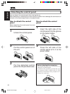
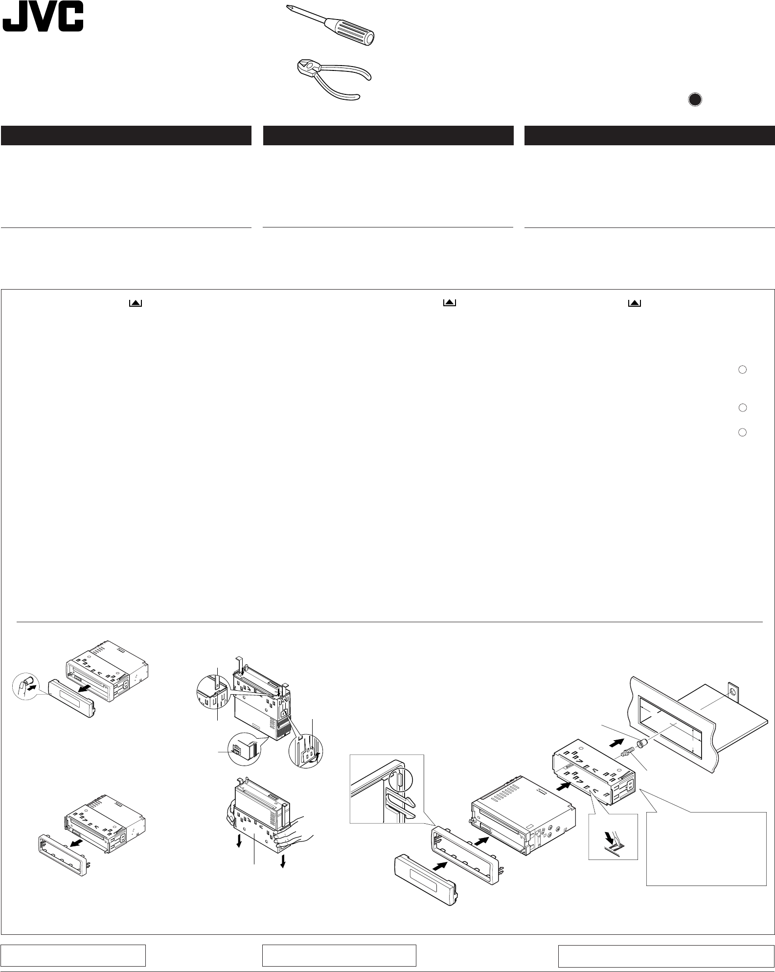
1
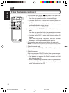
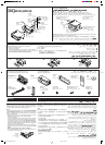
Before mounting: Press (Control Panel Release) to
detach the control panel if already attached.
* When shipped from the factory, the control panel is packed
in the hard case.
2
Remove the trim plate.
3
Remove the sleeve after disengaging the sleeve locks.
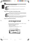
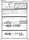
1 Stand the unit.
Note: When you stand the unit, be careful not to damage
the fuse on the rear.
2 Insert the 2 handles between the unit and the sleeve, as
illustrated, to disengage the sleeve locks.
3 Remove the sleeve.
Note: Be sure to keep the handles for future use after
installing the unit.
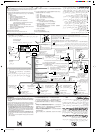
4
Install the sleeve in the dashboard.
* After the sleeve is correctly installed in the dashboard,
bend the appropriate tabs to hold the sleeve firmly in place,
as illustrated.
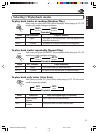
5
Fix the mounting bolt to the rear of the unit’s body and place
the rubber cushion over the end of the bolt.
6
Do the required electrical connections explained on the back
of this instructions.
7
Slide the unit into the sleeve until it is locked.
8
Attach the trim plate plate so that the projection on the trim
plate is fixed to the left .
9
Attach the control panel.
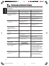
TROUBLESHOOTING
• The fuse blows.
* Are the red and black leads connected correctly?
• Power cannot be turned on.
* Is the yellow lead connected?
• No sound from the speakers.
* Is the speaker output lead short-circuited?
• Sound is distorted.
* Is the speaker output lead grounded?
* Are the “–” terminals of L and R speakers grounded in common?
• Unit becomes hot.
* Is the speaker output lead grounded?
* Are the “–” terminals of L and R speakers grounded in common?
Õöô«Ë ‰UDŽô« sŽ Y׳«Õöô«Ë ‰UDŽô« sŽ Y׳«
Õöô«Ë ‰UDŽô« sŽ Y׳«Õöô«Ë ‰UDŽô« sŽ Y׳«
Õöô«Ë ‰UDŽô« sŽ Y׳«
•
Æ“uOH« ‚d²×¹Æ“uOH« ‚d²×¹
Æ“uOH« ‚d²×¹Æ“uOH« ‚d²×¹
Æ“uOH« ‚d²×¹
*ø`O× qJAÐ Wuu œuÝô«Ë dLŠô« pK« q¼
•
ÆWOzUÐdNJ« WUD« qOuð sJ1 ôÆWOzUÐdNJ« WUD« qOuð sJ1 ô
ÆWOzUÐdNJ« WUD« qOuð sJ1 ôÆWOzUÐdNJ« WUD« qOuð sJ1 ô
ÆWOzUÐdNJ« WUD« qOuð sJ1 ô
*øôuu dHô« pK« q¼
•
ÆUŽUL« s u —bB¹ ôÆUŽUL« s u —bB¹ ô
ÆUŽUL« s u —bB¹ ôÆUŽUL« s u —bB¹ ô
ÆUŽUL« s u —bB¹ ô
*øWŽUL« Ãdš pKÝ …dz«œ w dOBIð pUM¼ q¼
•
ÆÁuA uB«ÆÁuA uB«
ÆÁuA uB«ÆÁuA uB«
ÆÁuA uB«
*ø÷—ôUÐ ôuu WŽUL« Ãdš pKÝ q¼
* Èd??O?« W?ŽU?L??K? å≠ò W?³?U??« ·«d?Þô« q¼L v?M?L?O?«Ë R
øiFÐ l ÷—ôUÐ Wuu
•
Æ“UN'« s¹Æ“UN'« s¹
Æ“UN'« s¹Æ“UN'« s¹
Æ“UN'« s¹
*ø÷—ôUÐ ôuu WŽUL« Ãdš pKÝ q¼
* Èd??O?« W?ŽU?L??K? å≠ò W?³?U??« ·«d?Þô« q¼L v?M?L?O?«Ë R
øiFÐ l ÷—ôUÐ Wuu
184 mm
53 mm
7
8
9
Trim plate
WM¹e« WŠu
4
*
4
6
5
See “ELECTRICAL
CONNECTIONS.”
r dE½«”öOu²«
WOzUÐdNJ«“Æ
2
1
1
0
3
Lock plate
XO³¦²« W×OH
Rubber cushion
WOÞUD*« …uA(«
Mounting bolt
VOd²« —UL
Dashboard
…—UO« uKÐUð
!"#$
1
!" !"#$%&'()* !"#
!"#$%&'(
* !"#$%&'()*+,&-./012
2
!"#
3
!"#$%&'()&*+
1 !"#
!"#$%&'()*+,-./01
2 !"#$%&'(%)*+,-./01234
!"#$%&'(
3 !"#$
!"#$%&'()*+,#-./01
4
!"#$%&'()
* !"#$%&'()*+,-./01-23!"4
!"#$%&'()*+,
5
!"#$%&&'()*+,-./0$ !"
!
6
!"#$%&'()%*+,-./01
7
!"#$ %&'()*+,-./
8
!"#$%&' !#()*+,-./0123
9
!"#$
!"
!
!
!
!"
!
• !"#
* !"#$%&'!"#$%()*$+ ?
• !"#$
* !"#$%&'$ ?
• !"#$
* !"#$%&'()*+ ?
• !"
* !"#$%&'() ?
* !"#$LR !"– !" ?
• !"
* !"#$%&'() ?
* !"#$LR !"– !" ?
• !"#$%12V !"#$%&'(
!"
!"#$%
• !"#$%&' ()*+,-./0123452
!"#$%&'()*+,-%./0 123.45
!"#$%&JVC !"#$%&'()*+,-
!"#
Sleeve
w«u« qJON«
Handle
WU*«
KD-SX975
KD-SX875
Installation/Connection Manual
O²O²
O²O²
O²
ÒÒ
ÒÒ
Ò
ØVO— X« ULOKFð VØVO— X« ULOKFð V
ØVO— X« ULOKFð VØVO— X« ULOKFð V
ØVO— X« ULOKFð V
qOu²«qOu²«
qOu²«qOu²«
qOu²«
Slot
oýÒdOG
Fuse
“uOH«
Sleeve
w«u« qJON«
InstalEn-KD-SX975.SX875[U]-8 18/01/2001, 08:43 PM1