


10 EN
JLIP
JLIP
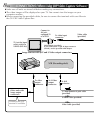
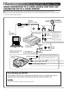
CONNECTIONS (When Using JLIP Video Producer Software)
WHEN CONNECTING TO A VIDEO SOURCE UNIT WITH JLIP
CONNECTOR OR TO A VIDEO PRINTER
Ⅲ Be sure to turn off the power of all connected units before making any connections.
Ⅲ When connecting the provided cable, be sure to connect the plug with the core filter to the
GV-CB3 Video Capture Box.
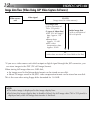
If you edit using a non-JVC VCR...
It is possible to use the remote control unit provided with your JVC camcorder. Also refer to
the camcorder’s instructions on connection and operation with your brand of VCR.
NOTE:
Some VCR brands or models cannot be operated.
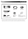
PC connection cable
(provided)
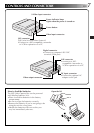
Rear panel
To digital
connector (8 pin)
To AC
outlet
AC adapter
(AA-V701EG/
EK) (optional)
To JLIP
connector
Core filter
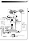
Front
panel
GV-PT2 Video
Printer
When connected with
the Video Printer
GV-CB3 Video
Capture Box
PC
To
COM port
(RS-232C)
To JLIP connector
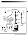
To JLIP
connector
To S-Video input connector
To video input connector
3.5 mm diameter
4-pole cable (provided)
Connect this if the video unit has
an S-Video output connector.
Connect this if
you are not
using batteries
in the Video
Capture Box.