


4
English
AM
LOOP
AM
EXT
ANTENNA
COAXIAL
FM 75
FM 75
COAXIAL
AM
LOOP
AM
EXT
ANTENNA
FM 75
COAXIAL
AM
LOOP
AM
EXT
ANTENNA
Getting Started
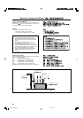
This section explains how to connect audio/video components and speakers to the receiver, and how to connect the
power supply.
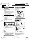
Before Installation
General Precautions
• Be sure your hands are dry.
• Turn the power off to all components.
•
Read the manuals supplied with the components you are going to connect.
Locations
• Install the receiver in a location that is level and protected from
moisture and dust.
• The temperature around the receiver must be between –5˚C and 35˚C.
• Make sure there is good ventilation around the receiver. Poor
ventilation could cause overheating and damage the receiver.
Handling the receiver
• Do not insert any metal object into the receiver.
• Do not disassemble the receiver or remove screws, covers, or cabinet.
• Do not expose the receiver to rain or moisture.
Checking the Supplied Accessories
Check to be sure you have all of the following items, which are
supplied with the receiver.
The number in the parentheses indicates quantity of the pieces supplied.
• Remote Control (1)
• Batteries (2)
• AM Loop Antenna (1)
• FM Antenna (1)
• AC Plug Adaptor (1)
If anything is missing, contact your dealer immediately.
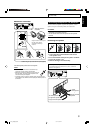
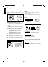
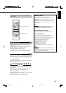
Putting Batteries in the Remote Control
Before using the remote control, insert the two supplied batteries first.
1 Press and slide the battery cover on the back of
the remote control.
2 Insert the batteries.
• Make sure to match the polarity: (+) to (+) and (–) to (–).
3 Replace the cover.
If the remote control cannot transmit signals or operate the receiver
correctly, replace the batteries. Use two R6(SUM-3)/AA(15F) type
dry-cell batteries.
Note:
Supplied batteries are for the initial setup. Replace for continued use.
CAUTION:
Follow these precautions to avoid leaking or cracking cells:
• Place batteries in the remote control so they match the
polarity: (+) to (+) and (–) to (–).
• Use the correct type of batteries. Batteries that look similar
may differ in voltage.
• Always replace both batteries at the same time.
• Do not expose batteries to heat or flame.
1
2
R6(SUM-3)/
AA(15F)
3
B
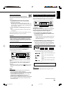
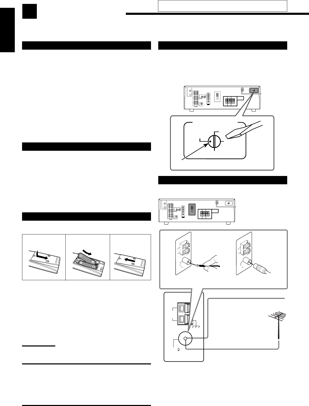
FM Antenna
(supplied)
Outdoor FM Antenna Cable
(not supplied)
Extend the supplied FM antenna
horizontally.
A
Do not connect the AC power cord until all other connections
have been made.
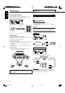
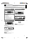
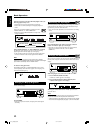
Adjusting the Voltage Selector
Before connections, always do the following first if necessary.
Select the correct voltage with the VOLTAGE SELECTOR switch
on the rear using a screw driver.
Check to be sure if the voltage mark is set to the voltage for the area
where you use this unit.
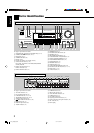
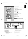
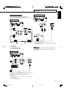
Connecting the FM and AM Antennas
FM antenna connections
Connect the supplied FM antenna as temporary measure to the
FM 75 Ω COAXIAL terminal—A
If reception is poor, connect the outdoor FM antenna (not
supplied)—B
1 Disconnect the supplied FM antenna.
2 Connect a 75 Ω coaxial cable with the standard type connector
(IEC or DIN45325).
VOLTAGE SELECTOR
220V
230
-
240V
127V
110V
Voltage mark
01-08_5052[US]2.p65 05.1.7, 5:03 PM4