


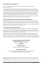
INPUT SENSITIVITY CONTROLS
Once the appropriate “Input Voltage” range
has been selected, the controls labeled “Input
Sens.” located in each “Channel Controls”
section can be used to match the source unit’s
output voltage to the input stage of each pair of
amplifier channels for maximum clean output.
Rotating the control clockwise will result in
higher sensitivity (louder for a given input
voltage). Rotating the control counter-clockwise
will result in lower sensitivity (quieter for a given
input voltage.)
To properly set the amplifier for maximum
clean output, please refer to Appendix A (page
14) in this manual. After using this procedure,
you can then adjust any or all “Input Sens.”
levels downward if this is required to achieve the
desired system balance.
Do not increase any “Input Sens.” setting for
any channel(s) of any amplifier in the system
beyond the maximum level established during
the procedure outlined in Appendix A (page
14). Doing so will result in audible distortion
and possible speaker damage.
FILTER CONTROLS
Most speakers are not designed to reproduce
the full range of frequencies audible by the
human ear. For this reason, most speaker
systems are comprised of multiple speakers, each
dedicated to reproducing a specific frequency
range. Filters are used to select which frequency
range is sent to each section of a speaker system.
The division of frequency ranges to different
speakers can be done with passive filters (coils
and/or capacitors between the amplifier outputs
and the speakers), which are acceptable and
commonly used for filtering between mid-
range speakers and tweeters. Filtering between
subwoofer systems and satellite speaker systems
is best done with active filters, which cut off
frequency content at the input to the amplifier.
Active filters are more stable than passive filters
and do not introduce extraneous resistance,
which can degrade subwoofer performance.
The active filter built into each channel section
of the G6600 can be used to eliminate potentially
harmful and/or undesired frequencies from
making their way through the amplifier sections
to the speaker(s). This serves to improve tonal
balance and to avoid distortion and possible
speaker failure. Correct use of these filters can
substantially increase the longevity and fidelity of
your audio system.
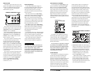
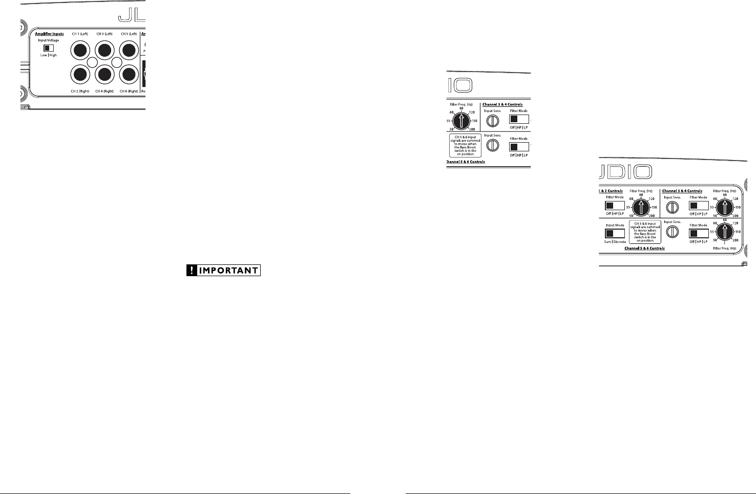
1) “Filter Mode” Control: The G6600 employs a
12dB per octave filter for each pair of channels
(one filter for channels 1&2, another filter for
channels 3&4 and a third filter for channels
5&6). Each of these filters can be configured
independently into one of two filter types
or defeated completely by way of the three-
position “Filter Mode” switches:
“Off”: Defeats the filter completely, allowing
the full range of frequencies present at the
inputs to feed the amplifier. This is useful
for systems utilizing outboard crossovers or
requiring full-range reproduction from one or
more of the G6600’s channel pairs.
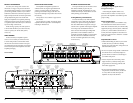
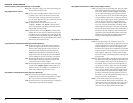
INPUT SECTION
The G6600’s input section allows you to send
signals to the amplifier section through the use of
two, four or six differential-balanced inputs.
Input connections are via three pairs of
traditional RCA-type jacks.
If you wish to send six discrete channels into
the G6600, simply use all six inputs and set the
“Input Mode” switch in the “Channel 5 & 6
Controls” section to “Discrete”.
If you wish to feed all six channels by using
only four channels of full-range input, set the
“Input Mode” switch in the “Channel 5 & 6
Controls” section to “Sum” and use only the
inputs to channels 1, 2, 3 & 4.
If you wish to feed all six channels by using
two channels of full-range input and two
channels of low-frequency input (subwoofer
output from the source unit), set the “Input
Mode” switch in the “Channel 5 & 6 Controls”
section to “Discrete”. It will be necessary to split
the full-range signals with y-adaptors and feed
these signals into the inputs to channels 1, 2, 3 &
4. The dedicated subwoofer signal should be sent
to channels 5 & 6.
If you wish to use only two channels of input
to deliver signal to all six amplifier channels,
it will be necessary to split the two signals with
y-adaptors and feed these signals into the inputs
to channels 1, 2, 3 & 4. Set the “Input Mode”
switch in the “Channel 5 & 6 Controls”
section to “Sum” and use only the inputs
to channels 1, 2, 3 & 4.
Input Voltage Range:
A wide range of signal input voltages can
be accommodated by the G6600’s CH 1&2 and
CH 3&4 input sections (200mV – 8V). This
wide range is split up into two sub-ranges,
accessible via a switch located to the left of the
Input Connectors.
The “Low” position on the “Input Voltage”
switch selects an input sensitivity range between
200mV and 2V. This means that the “Input
Sens.” rotary control will operate within that
voltage window. If you are using an aftermarket
source unit or an OEM interface processor with
conventional preamp-level outputs, this is most
likely the position that you will use.
The “High” position on the “Input Voltage”
switch selects an input sensitivity range between
800mV and 8V. This is useful for certain high-
output preamp level signals as well as speaker-
level output from source units and
small amplifiers.
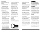
To use speaker-level sources, splice the speaker
output wires of the source unit or small amplifier
onto a pair of RCA plugs for each input pair.
No line output converter is needed in most cases.
The CH 5&6 input section is designed to
accept only line-level signals and may clip
(distort) if high-level signals are applied to it.
The output of the amplifier will decrease for
a given input voltage when the “Input Range”
switch is placed in the “High” position.
Conversely, the output will be higher with the
switch in the “Low” position. While this may
sound counter-intuitive, it is consistent with
the descriptions above.
6 JL AUDIO G6600 JL AUDIO G6600 7