


SYSTEM CONFIGURATIONS
The G6600 is a flexible amplifier, well-suited
for a multitude of system configurations. In
this section, the most likely configurations are
explained in detail.
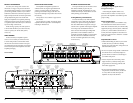
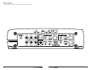
Once you have selected your desired
configuration, you can use the amplifier panel
drawing on pages 18 & 19 to mark the required
switch positions for easy reference.
BIAMPLIFIED SYSTEMS
Bi-amplified systems are defined as systems
in which separate amplifier channels drive low-
frequency (LF) and high-frequency (HF) speakers
and are separately filtered to send appropriate
frequency ranges to each speaker system.
The most common application of bi-
amplification in mobile audio is to drive a
subwoofer system from one or more amplifiers or
channels and component speakers from separate
amplifiers or channels.
The G6600 is designed to work as the only
amplifier in a bi-amplified system.
Bi-Amplified System with the G6600
In this configuration, channels 5&6 of the
G6600 will drive subwoofers (stereo 75W x 2 at 2
ohms or bridged 150W x 1 at 4 ohms) with low-
pass filtering. Channels 1&2 and channels 3&4
will drive component speakers in stereo (75W x 4
at 2 ohms) with high-pass filtering.
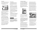
Input connection options for a bi-amplified system
with one G6600 are as follows:
A) No User Adjustability:
R e q u i r e d : a basic source unit or processor
with one pair of stereo outputs.
Inp ut Connections: a single pair of stereo source
unit outputs each split with a “Y-Adaptor”
allowing the left signal to be sent to the
“CH 1 (Left)” and “CH 3 (Left)” inputs and
the right signal to be sent to the “CH 2 (Right)”
and “CH 4 (Right)” inputs of the G6600 (select
“Sum” on the “Input Mode” switch in the
“Channel 5 & 6 Controls” section).
R e s u l t : the relative level of the LF and HF
channels will be fixed by the G6600’s “Input
Sens.” settings and will not be user adjustable
from the front of the vehicle.
B) Fade Front vs. Rear with no Subwoofer
Level Control:
R e q u i r e d : a basic source unit or processor with
two pairs of stereo outputs.
Inp ut Connections: one pair of stereo source unit
outputs is connected to the “CH 1 (Left)” and
“CH 2 (Right)” inputs and the second pair
of stereo source unit outputs is connected
to the “CH 3 (Left)” and “CH 4 (Right)”
inputs of the G6600 (select “Sum” on the
“Input Mode” switch in the “Channel 5 & 6
Controls” section).
R e s u l t : the relative level of the LF and HF
channels will be fixed by the G6600’s “Input
Sens.” settings and will not be user adjustable
from the front of the vehicle.
C) Fade Subwoofer Level vs. HF Level:
R e q u i r e d : a basic source unit or processor with
two pairs of stereo outputs.
Inp ut Connections: the first stereo pair of source
unit outputs each split with a “Y-Adaptor”
allowing the left signal to be sent to the “CH
1 (Left)” and “CH 3 (Left)” inputs and the
right signal to be sent to the “CH 2 (Right)”
and “CH 4 (Right)” inputs of the G6600.
The second stereo pair of source unit outputs
is connected to the “CH 5 (Left)” and “CH
6 (Right)” inputs (select “Discrete” on the
“Input Mode” switch in the “Channel 5 & 6
Controls” section).
R e s u l t : in this mode, the user has the ability to
fade or control the level of the LF channels
relative to the HF channels via the source
unit’s fader control without exceeding the
maximum clean output level set by each
amplifier section’s “Input Sens.” controls.
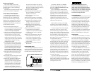
AMPLIFIER STATUS INDICATOR LIGHTS &
PROTECTION CIRCUITRY
There are two status indicator lights on the
input / control end of the amplifier.
1) “Power” (Green): lights to indicate that the
amplifier is turned on and operating normally.
2) “Protect” (Red): Indicates that the amplifier
protection circuitry has been activated to
prevent product failure due to a short-circuit
or a dangerously low impedance connected
to the amplifier output(s). Connecting the
speaker outputs to an impedance lower than
2 ohms stereo (4 ohms bridged) will cause
this protection mode to activate. When this
protection mode is activated, the amplifier will
reduce it maximum power output to protect its
circuitry, which will manifest itself as increased
distortion. When the problem is corrected, the
amplifier will return to normal operation.
Advanced Rollback Thermal protection
Unlike conventional thermal protection
systems, which shut down an amplifier when it
overheats, this system protects the amplifier by
gradually reducing power output if the amplifier’s
safe operating temperature is exceeded. The
amplifier will continue to operate and return
to normal power output once its temperature
returns to a normal range.
Low-Voltage protection:
If the car’s supply voltage drops below 10
volts, the entire amplifier will shut itself off to
protect its internal circuitry. The green “Power”
indicator will turn off when this occurs. The
amplifier will turn back on when voltage climbs
back above 10 volts. This may happen in a rapid
cycle when bass-heavy program material causes
a weak charging system to dip below 10 volts
momentarily. If this is happening in your system,
turn your audio system off and have your power
wiring, ground connections and charging
system inspected.
SERVICING YOUR JL AUDIO AMPLIFIER
If your amplifier fails or malfunctions, please
return it to your authorized JL Audio dealer so
that it may be sent in to JL Audio for service.
There are no user serviceable parts or fuses inside
the amplifier. The unique nature of the circuitry
in the JL Audio amplifiers requires specifically
trained service personnel. Do not attempt
to service the amplifier yourself or through
unauthorized repair facilities. This will not only
void the warranty, but may result in the creation
of more problems within the amplifier.
If you have any questions about the installation or
setup of the amplifier not covered in this manual,
please contact your dealer or technical support.
JL Audio Technical Support:
(9 5 4) 4 43 -110 0
9:00 AM – 5:30 PM (Eastern Time Zone)
Monday - Friday
10 JL AUDIO G6600 JL AUDIO G6600 11