


© Jeff Rowland design gRoup 2007. all Rights ReseRved.
11
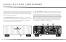
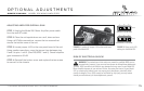
(3) LOUDSPEAKER OUTPUT: Unscrew the knob that secures the speaker output connector
and pull the securing block out far enough to allow access to the binding posts. Install the
positive (usually red) loudspeaker cable spade terminal to the positive (+) binding post and the
negative spade terminal to the negative (-) binding post. Secure the loudspeaker connections
by tightening the knob securely with your fingers. The Model 201 will only accept spade termi-
nated loudspeaker cables. Banana plugs or bare wire connections can be used but require an
optional clamp available from your JRDG Dealer.
(4) AC INPUT CONNECTOR: Verify that the VOLTS AC input identified on the rear panel near
the AC input socket is the same as the AC mains voltage in your area. If the voltage does not
match, DO NOT CONNECT THE AMPLIFIER TO AC POWER and contact your dealer immediately.
Install the AC Power Cable between the AC input connector and your AC mains outlet.
(5) MASTER AC POWER SWITCH:
This switch controls the
operating status of the amplifier.
Pressing the “I” symbol on the switch will turn the amplifier
ON
. Pressing the “
O
” symbol on
the switch will turn the amplifier
OFF
.
Signal & power connectionS
OWNER’S MANUAL MODEL 201 MONO AMPLIFIER
WARNING: