


Amplifier Rear Panel Power ConnectionsAmplifier Rear Panel Power Connections
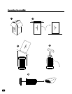
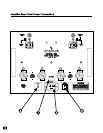
Important: Please strictly follow the following steps outlined below in order before operating your
Model 302 Stereo Power Amplifier.
K Verify that the VOLTS AC input identified on the rear panel near the AC input socket is the
same as the AC mains voltage in your area. If the voltage does not match, DO NOT
CONNECT THE AMPLIFIER TO AC POWER and contact your dealer immediately.
L Verify that the AC MAINS circuit breaker is closed (no white area visible on breaker).
M Install the AC Power Cable between the amplifier and your AC mains outlet.
N Connect the 12V Remote ON/OFF Mini-plug Connector (See Below).
Note: Due to the exceptionally low power consumption rating of the Model 302, it is recommended
that the unit not be disconnected from AC mains unless the amplifier is to be moved or reinstalled in
another location. It is recommended that the amplifier be placed in Standby mode rather than
disconnected from the AC mains power when the amplifier is not in use.
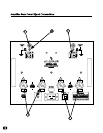
1717
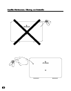
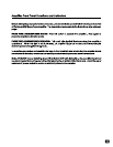
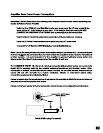
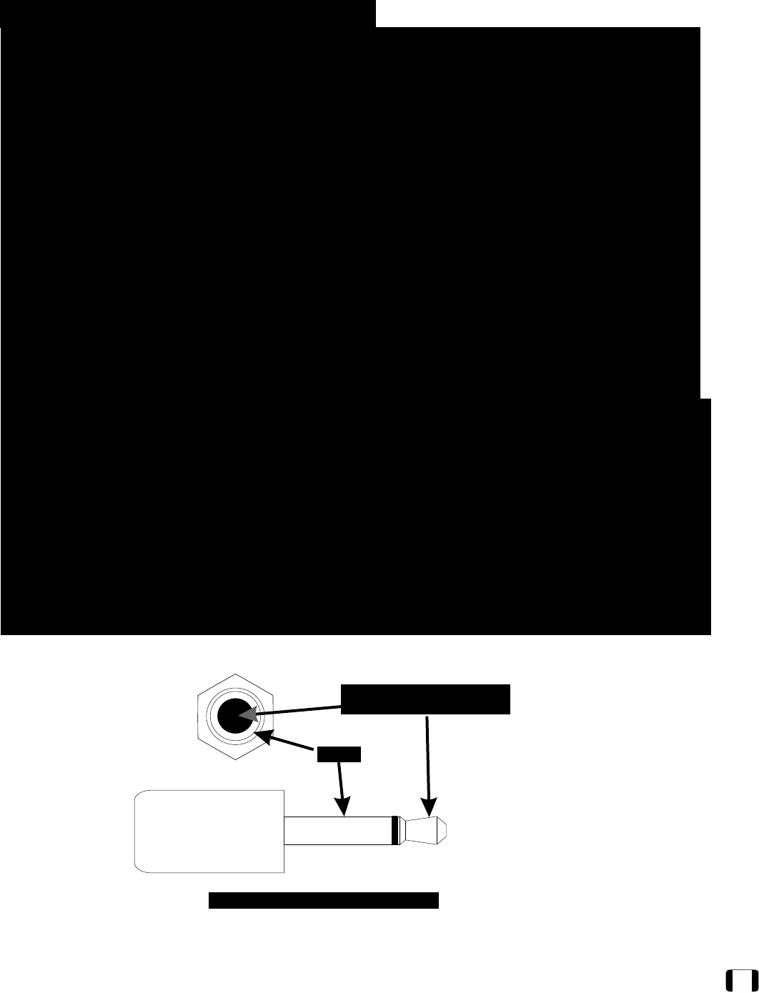
The 12V REMOTE ON/OFF 1/8” (3.5 mm) mini-plug connector (4) is provided on the rear panel of the
Model 302 for remotely switching the amplifier between Operational and Standby modes. When
connected to another component with the proper circuitry, the amplifier standby function can be
turned ON and OFF remotely in a custom installation, theater, or automated system setup.
Connection requirements are illustrated below.
Please be aware that the remote feature simply places the amplifier in STANDBY mode and does not
disconnect the unit from power or AC mains.
Please contact your dealer for further information about the use and configuration of this feature.
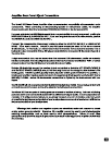
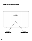
Constant 3V to 15V DC Signal
(12VDC Typical)
Constant 3V to 15V DC Signal
(12VDC Typical)
GroundGround
Detail of Mini-plug ConnectorDetail of Mini-plug Connector