


19
JBL Professional
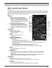
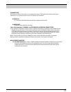
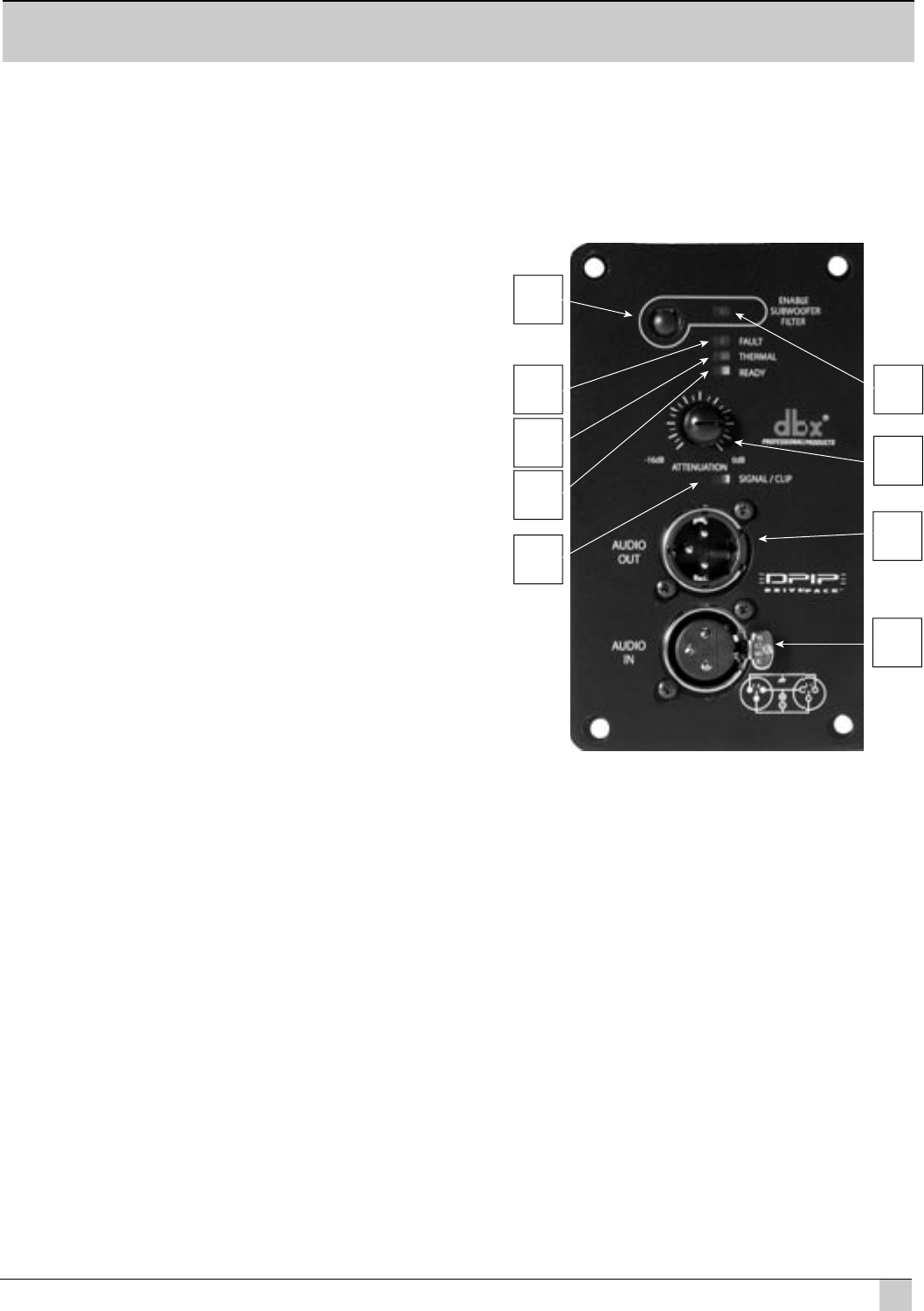
DPIP – Standard Input Module
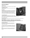
See Figure 1
The standard DPIP input module features analog audio inputs and sophisticated onboard digital signal processing
technology. Precision Bandpass limiting, pre-equalization fi lters and automatic self-test functions ensure optimized
performance. JBL engineers have calibrated DSP speaker management and limiter parameters to insure smooth
phase response and transfer function curves right out of the
box.
CONTROLS
1) Subwoofer Filter Enable Select Switch
a) Momentary, Enables or disables the selected
function. On subwoofer applications the low-pass
frequency is set to 80 Hz and for full range systems
the high-pass is raised to 80 Hz. (Knee shape and
slopes are model dependent).
7) Input Sensitivity/Attenuation Control:
a) 16 dB Precision Detented rotary control, 0.5 dB
steps. Sensitivity +4 dBu nominal (+23 dBu clip)
with the control fully counter clockwise, and -10
dBv nominal (+4 dBu clip) with the control fully
clockwise.
INDICATORS
2) Subwoofer Filter Enable
a) Orange LED, illuminates when the
function is enabled.
3) FAULT
a) Red LED, illuminates during any
fault condition.
4) THERMAL PROTECTION
a) Orange LED, illuminates during
thermal limiting:
ai) PULSING indicates fi rst stage of thermal
limiting, amplifi er output level is reduced to prevent overheating.
aii) FLASHING indicates transducer thermal limits have been exceeded. Further reduction in
output level is applied.
aiii) SOLID illumination indicates thermal protection is in the third stage of
protection and amplifi er shut down may occur if immediate
action is not taken to correct the external reason for excessive heating of the amplifi er.
5) Ready
a) Green LED, illuminates when the system is
ready for operation.
6) SIGNAL/CLIP
a) (Signal) Green LED, detects input signal above the threshold set at –70 dBu. b) Yellow indicates
that the audio drive signal has exceeded limits preset in DSP on any channel and compression/
limiting is active.
c) (Clip) Red LED, Clip detection monitors input, DSP, and each amplifi er output channel. The LED
changes from Green to Red when clipping THD at any point is detected.
CONNECTORS
8) Audio In
a) F-XLR Active 20K Ohm Balanced, 10K Ohm Unbalanced.
b) Pin 2 Hot (Positive voltage produces outward cone motion of L.F. Transducers).
9) Audio Out
a) M-XLR Passive Audio Pass-through.
b) Pin 2 Hot (Positive voltage produces outward cone motion of L.F. Transducers).
Figure 1