


20
VERTEC User’s Guide
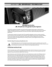
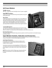
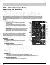
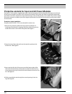
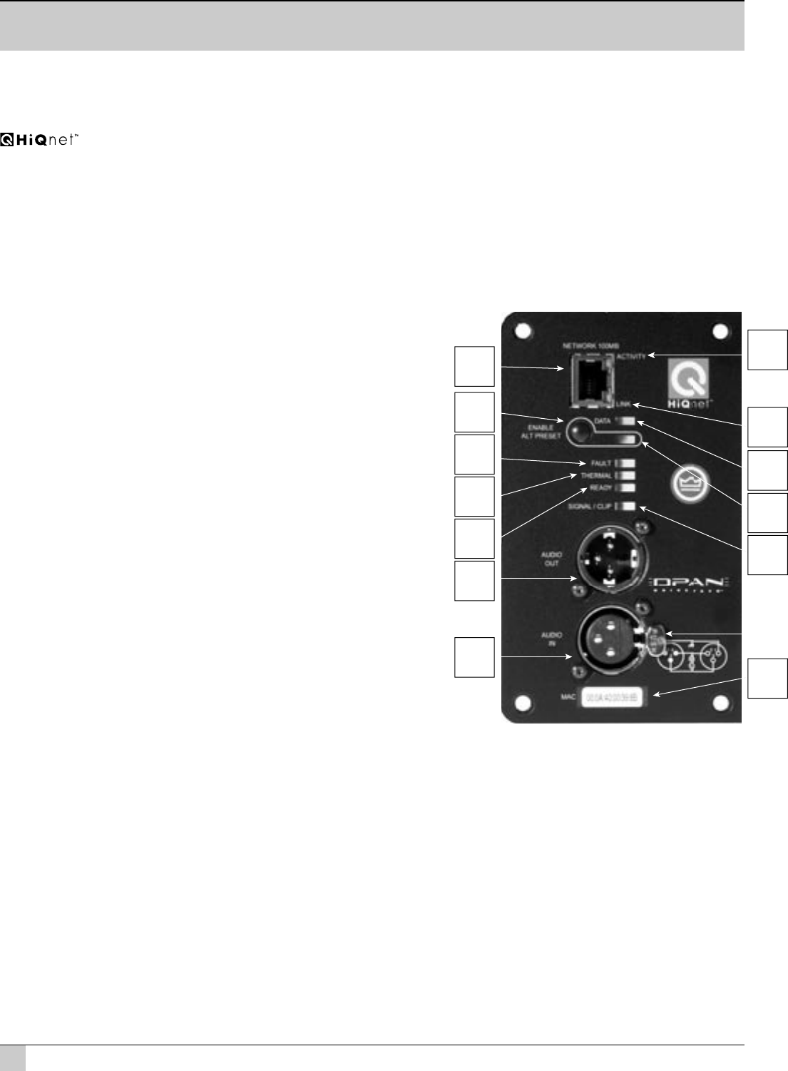
DPAN – HiQnet Network Input Module,
Analog Audio with Networking
See Figure 1a
The DPAN input module features analog audio inputs and sophisticated onboard digital signal processing
technology. Precision band pass limiting, pre-equalization fi lters and automatic self-test functions ensure optimized
performance. In addition, the DPAN input module adds 100 Mb Ethernet networking functionality and HiQnet
compatibility. It enables remote control and monitoring via HiQnet System Architect™ software. Network Control and
Monitoring is enabled by the JBL DP-DCP (DrivePack Device Control Panel) supplied within HiQnet System Architect.
Network capabilities include monitoring of status, input and output levels, clipping, temperature, load faults and gain
reduction. Additional control features available in software include load supervision, dynamic processing, ten internal
user defi ned presets, delays, onboard noise and sine-wave generators, network device event logging, and user alert
messaging.
CONTROLS
1) ENABLE ALT PRESET button
a) Momentary, Enables or Disables the selected function.
Factory ALT Preset:
On subwoofer applications, the subwoofer low-pass fi lter
frequency is set to 80 Hz and for full range systems the high-
pass is raised to 80 Hz. (Knee shape and slopes are model
dependent).
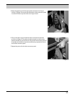
Internal Controls - Input Sensitivity 2-Position Switch: Located
on the back side of the front panel, full output is achieved by
selecting either +4 dBu in one position or +20 dBu in the other
position. Switch positions are marked with silkscreen on the
PWB.
NOTE: Product is shipped factory set to the +20 dBu switch position
to provide optimal input gain structure and headroom for most
professional audio equipment. Changing the sensitivity switch to the
+4 dBu setting is not recommended unless connection to -10 dBV
equipment is required.
INDICATORS
2) ENABLE ALT PRESET
a) Orange LED illuminates when the function is enabled.
3) FAULT
a) Red LED illuminates during any fault condition.
4) THERMAL Protection
a) Orange LED illuminates during thermal limiting:
ai) FLASHING indicates fi rst stage of thermal limiting, amplifi er output level is reduced to prevent
overheating.
aii) SOLID illumination indicates thermal protection is in the second stage of protection and
amplifi er shut down may occur if immediate action is not taken to correct the external reason for
excessive heating of the amplifi er.
5) READY
a) Green LED, illuminates when the system is ready for operation
6) SIGNAL/CLIP
a) (Signal) Green LED, detects input signal above the threshold set at –70 dBu
b) (Clip) Red LED, Clip detection monitors input, DSP, and each amplifi er output channel. The LED
changes from Green to Red when clipping THD at any point is detected.
11) NETWORK 100MB ACTIVITY
a) The Activity LED indicates data activity on the network line.
Figure 1a