


10
3.0
OPERATION AND
CONTROLS
3.0
OPERATION AND
CONTROLS
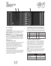
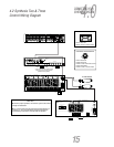
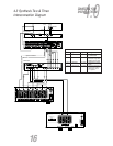
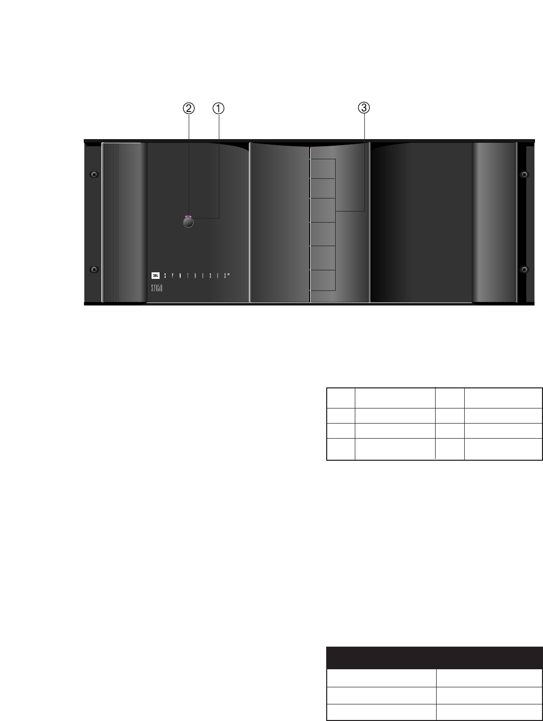
3.1 S7150
1. Power Switch
Pushing this button is all that is required to turn on the
S7150 if it is not part of a Synthesis system and the
Manual On/Auto On switch (rear panel) is in the
Manual On position. If the amplifier is used as part of
a JBL Synthesis System, and the Manual On/Auto
On switch is in the Auto On position, the amplifier
will turn on when the surround processor is activated.
The front panel pushbutton power switch is left in the
ON (in) position.
2. Standby Indicator (red)
This indicator, immediately above the front panel power
switch, will glow red when the amplifier is in the
"standby" mode, whether operating as part of a
Synthesis system or not. When the S7150 is in the
"operate" mode, this light will shut off and the blue
"operate" mode indicators will light..
3. Power Indicators (blue)
These indicators will light up when the power amplifier
is in the "operate" mode. Each monitors the operation
of one channel, and will extinguish if that channel’s
protective circuit is activated.
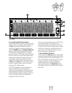
4. Input Jacks (Ch.1 thru Ch.7) (see page 11)
Seven of the output signals from the Synthesis digital
processor and equalizer are connected to the seven input
jacks. We suggest the channels be assigned as follows:
5. Speaker Terminals (see page 11)
Connect the speakers to these terminals, following the
normal convention; wire the "+" side of the speaker to
the red terminal, and the "-" side to the black terminal.
Wire the speakers with the proper polarity; reversing
any speaker’s connections will not damage either the
speaker or the amplifier, but will result in poor low
frequency performance and imprecise imaging.
NOTE: The minimum load impedance that this amplifier
can handle safely is two ohms per channel. Using lower
impedance loads can damage the unit and will void
your warranty!
Wire Run Length Rec. Ga.
Up to 20' 16
Up to 50' 14
Up to 100' 12
Wire Run Length Minimum Gage
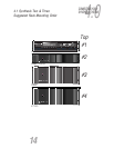
Ch. 1 Right Rear (Processor) Ch. 5 Left Front (Equalizer)
Ch. 2 Right Side (Equalizer) Ch. 6 Left Side (Equalizer)
Ch. 3 Right Front (Equalizer) Ch. 7 Left Rear (Processor)
Ch. 4 Center (Equalizer)