8
®
3.0
S5160 OPERATION AND
CONTROLS
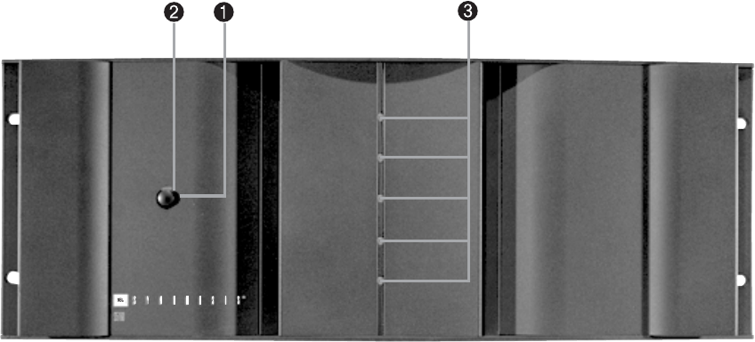
1. Power Switch
Pushing this button is all that is required to turn on the
S5160 if it is not part of a Synthesis system and the
Manual On/Auto On switch
(rear panel) is in the
Manual On position. If the amplifier is used as part of a
JBL Synthesis system, and the Manual On/Auto On
switch
is in the Auto On position, the amplifier will
turn on when the surround processor is activated. In this
application, the front-panel pushbutton Power switch
should be left in the ON (in) position. See the description
of the Manual On/Auto On switch
for more infor-
mation on turning on the S5160.
2. Standby Indicator
This indicator, immediately above the front-panel Power
switch, will glow red when the amplifier is in the “standby”
mode, whether operating as part of a Synthesis system
or not. When the S5160 is in the “on” mode, this light will
shut off and the blue “on” mode indicators will light.
3. Power Indicators (Blue)
These indicators will light up when the power amplifier
is in the “on” mode. Each monitors the operation of one
channel, and will be extinguished if that channel’s
protection circuitry is activated.
4. Input Jacks (Ch.1 Through Ch.5)
The output signals from the Synthesis digital processor and
equalizer are connected to the input jacks in a Synthesis
One system. We suggest that the channels be assigned
as follows:
Amplifier #1:
Channel 1 Center Low-Frequency
Channel 2 Center High-Frequency
Channel 3 Right Front Low-Frequency
Channel 4 Right Front High-Frequency
Channel 5 Right Rear Surround
Amplifier #2:
Channel 1 Right Side Surround
Channel 2 Left Side Surround
Channel 3 Left Front Low-Frequency
Channel 4 Left Front High-Frequency
Channel 5 Left Rear Surround
S5160 OM 5/31/05 2:15 PM Page 8


