


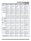


17
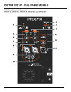
FEATURES
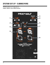
1. Selectable System EQ
a. Normal and Boost (PRX710, PRX725, & PRX735 only) – When set in the “Normal” position, frequency
response is linear and unaltered. When “Boost” is selected, internal equalization is applied to enhance low
frequency and high frequency response. “Normal” will provide greater accuracy of reproduced music and
higher speech intelligibility. “Boost” is particularly useful at lower levels to enhance the low and high
frequencies of pre-recorded music. This feature provides exibility without the need to use an
external equalizer. The LED will illuminate GREEN when NORMAL is selected and YELLOW when
BOOST is selected.
b. Main and Monitor (PRX712 & PRX715 only) – Switching between “Main” and “Monitor” optimizes the
system for use as either a main full-range system or a stage monitor. The LED will illuminate GREEN
when MAIN is selected and YELLOW when MONITOR is selected.
2. PWR/STBY LED – This LED illuminates when the “Power Switch” has been turned to the on position. It will
illuminate BLUE when the system has power and is ready to pass audio. It will illuminate RED when the
system is in power save mode and not passing audio.
3. FRONT LED – This push button allows you to turn on/off the Power LED on the front of the speaker. The
front LED will illuminate BLUE when the system has power and is ready to pass audio. When the front LED
turn RED that means the system is in power save mode and not passing audio.
4. SIGNAL Indicator – There are two LED indicators (one for each channel) that will illuminate GREEN when
signal is present at the input connector.
5. LIMIT Indicator – There is one YELLOW LED indicator that will illuminate when peak output has been
reached and the DSP limiter is acting.
6. GAIN Knobs – This gain knob is for setting the input level of CH1 and CH2.
7. MIC/LINE Button – This push button allows you to choose between MIC or LINE level on CH1 only. CH2 is
always line level.
8. GROUND LIFT Button – This push button allows you to lift the ground on CH2 only reducing unwanted hum
and buzz caused by ground loops in the system.
9. XLR Inputs – Female balanced XLR and 1/4 inch phone jack combo input connectors.
10. RCA Inputs – Female unbalanced RCA input connectors.
11. SPK SELECT Switch – This switch determines which inputs are fed through to the amplier. If CH1 is
selected only the audio on CH1 will pass through to the speaker. If CH2 is selected only the audio on CH2
will pass through to the speaker. If MIX is selected, the audio on both CH1 and CH2 will pass through to
the speaker.
12. THRU SELECT Switch – This switch determines which inputs are sent out of the THRU connector. If CH1
is selected, only the audio on CH1 will be sent out via the THRU connector. If CH2 is selected, only audio
on CH2 will be sent out via the THRU connector. If MIX is selected, the audio on both CH1 and CH2 will be
sent out via the THRU connector at a 50/50 mix. The signal sent out of the THRU connector is before the
GAIN knob so any change in level via the GAIN knob will not be reected on the signal that is sent out.
13. THRU Connector – Male balanced XLR output connector. This connector provides a full-range signal
which can be daisy chained to another speaker.