


4 5
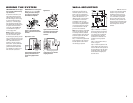
WIRING THE SYSTEM
IMPORTANT: Make sure all equip-
ment is turned off before making
any connections.
For speaker connections, use a
high-quality speaker wire with
polarity coding. The side of the
wire with a ridge or other coding
is usually considered positive
polarity (i.e., +). Heavier-gauge
wire should be used when more
than 50 feet (15m) of speaker wire
is required. The wire channels
on the rear of the P52OWS will
accommodate most types of
14- to 18-gauge wire.
NOTE: If desired, consult your
local JBL dealer about speaker
wire and connection options.
To ensure proper polarity, connect
each + terminal on the back of the
amplifier or receiver to the respec-
tive + (red) terminal on each
speaker, as shown in Figure 8.
Connect the
–
(black) terminals in
a similar way. See the owner’s
guides that were included with
your amplifier or receiver to con-
firm connection procedures.
IMPORTANT: Do not reverse polar-
ities (i.e., + to
–
or
–
to +) when
making connections. Doing so
will cause poor imaging and
diminished bass response.
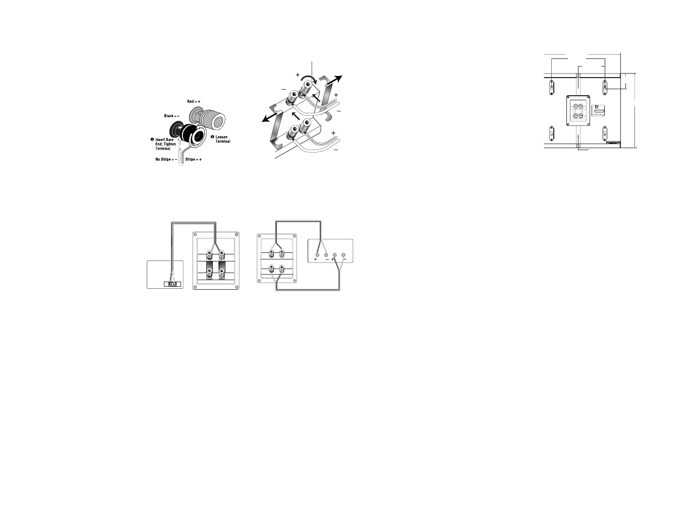
Figure 7. This example shows
how to connect bare wires to the
terminals.
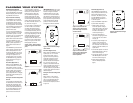
Applications 1 and 2
Figure 8. Wiring diagram shows
polarity connections for one
channel using Applications 1
and 2.
Application 3
Figure 9. Loosen the terminals
and remove the strapping bars
that connect the two sets of
terminals.
Figure 10. Wiring diagram shows
connections for two channels
using Application 3.
+
+
–
–
Receiver/
Amplifier
Right Rear
Speaker
Left Rear
Speaker
Right
Rear
Left
Rear
+–
Receiver or
Amplifier
(rear view)
+
–
Speaker
(rear view)
(one channel shown)
The JBL P52OWS speaker is
designed to mount directly to a
wall. Each speaker has four key-
holes in the rear to allow either
left- or right-side placement. Each
speaker will require two 1-1/2"
(38mm) #8 wood screws fastened
to a wall stud. If a wall stud is
unavailable, install an anchor
appropriate for a 1-1/2"(38mm) #8
screw. Use the supplied template
to accurately position the screws
on the wall and refer to the dia-
grams for more assistance.
NOTE: The customer is responsible
for the correct selection and use
of mounting hardware (available
through hardware stores) that will
ensure the proper and safe wall-
mounting of the speakers.
Step 1 – Position the supplied wall-
mount template on the wall in the
desired speaker location. Make
two markings per speaker.
Figure 11.
Step 2 – Fasten (2) 1-1/2"(38mm),
#8 wood screws to the wall using
the markings placed in Step 1 as
your guide. Leave a 3/16" (5mm)
space between the wall and
screwhead. If a wall stud is not
available, use an appropriate
anchor.
Step 3 – Attach speaker wire, as
shown on page 4.
Step 4 – Place the speaker on the
wall by aligning the upper two key-
holes on the back of the speaker to
the screwheads on the wall. Once
positioned properly, the speaker
should slide down slightly and
become secure.
IMPORTANT NOTE: The set of driv-
ers closer to the monopole setting
indicator in Figure 3 should be
installed toward the front of the
room. It does not matter whether
or not the tweeter is positioned
above or below the woofer. This
will ensure proper operation and
performance should the Monopole
or Dipole position on the surround
mode configuration switch be
selected.
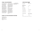
8-3/8" (213mm)
11-13/16" (300mm)
2-7/16"
(62mm)
13-3/4"
(349mm
)
Wire Channel
4-3/16" (107mm)
P520OWS
Serial #
Nominal Impedence: 8 ohms
JBL
Northridge, California, USA
PATENT PENDING
WALL-MOUNTING