Simultaneous Stereo-Mono
Connection Diagrams
11
L– L+
L L LR R R
– +
L– R+
– +
R– R+
– +
2 or 4-Ohm
Full-Range
Speakers
4-Ohm
Subwoofer
Amp Crossover Input Mode Preamp
Switch Switch Output
Crossover
A High Pass Stereo Flat
B Low Pass L + R Doesn't Matter
Speaker Output
GTS300/600
A
GTS300/600
B
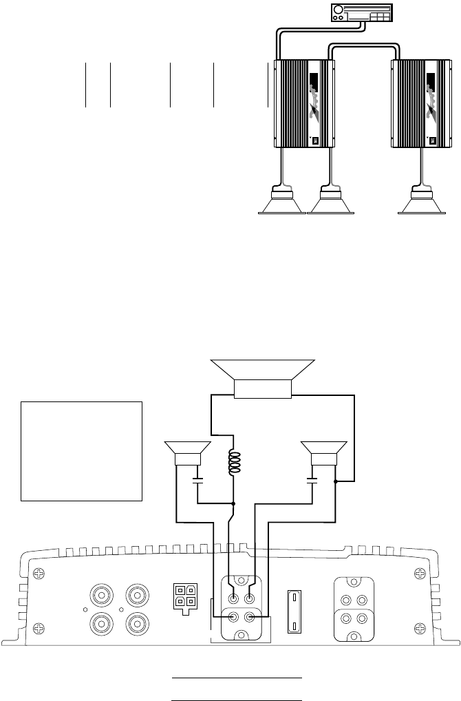
Application 4
Bi-amplified System Using
Preamp Output Capability.
Preamp or
Speaker-Level
Input
Preamp
Output
Preamp
Intput
Stereo Subwoofers may be used by configuring
Amp B as shown in Application #1 or by
using dual GTS amplifiers as shown in
Application 2.
M
A
D
E
I
N
T
H
E
U
S
A
M
A
D
E
I
N
T
H
E
U
S
A
Application 4
Bi-amplified, System Using
Preamp Output Capability
(+)
(+)
(–)
(–)
(+)
(–)
C C
L
Subwoofer (Low Pass)
Tweeter/Midrange Satellites
(High Pass)
High Pass Satelite
Crossover Frequency: 100Hz
C: 300µF capacitor
100V, non polorized
Subwoofer Low pass
Crossover Frequency: 100Hz
L: 6.2mH air core inductor
Right
Left
40A
LINE
INPUT
PREAMP
OUTPUT
LL
R
RR
SPEAKER LEVEL
INPUT
SPEAKER
OUTPUT POWER
FUSE
40A
BRIDGED
+
_
R
+
L
+
_
+
_
BATT(+)
REM OUTREM IN
GND
Component Values for
4 Ohm Loudspeakers*
GTS300 or GTS600
A. Satellite/Subwoofer
*You may change the subwoofer satelite crossover frequency by using the Inductor and Capacitor values calculated
with the following formulas:
High Pass (Satelite Crossover): = New Capacitor Value in µF
30,000
Desired crossover Frequency in Hz
Low Pass (Subwoofer Crossover): = New Inductor Value in mH
620
Desired crossover Frequency in Hz
L


