


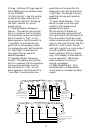
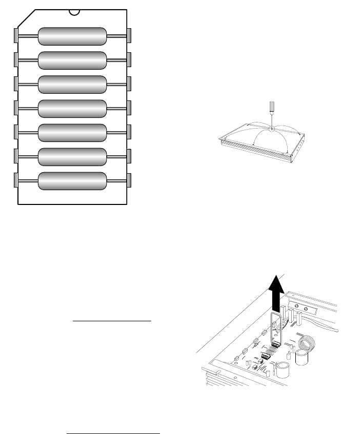
Regardless of whether you build
or buy it, the necessary resistor
network has the following
configuration:
Custom “Chip” Construction
• Each resistor in the package has
the same value.
• If you kvow the crossover
frequency you want, you can
calculate the resistor value
necessary by solving the
following equation:
Resistor 2,500,000
Value = Crossover
in Ohms Frequency in Hz
• Use the following equation if
you have a resistor pack of a
known value, and want to find
it’s crossover frequency:
Crossover 2,500,000
Frequency = Crossover
in Hz Resistor Value in Ohms
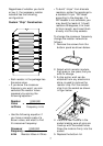
• To build “chips” from discrete
resistors, solder the resistores to
a standard 14-pin “DIP Head”
according to the diagram. If a
DIP Header is not available, you
may bend the leads of 1/4 watt
resistors 90 degrees, trim them
to 3mm-length, and insert them
directly into the chip sockets.
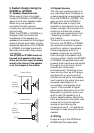
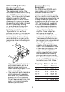
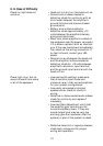
To change the crossover frequency
change the resistor network as
follows:
1. Remove the screws from the
bottom panel as shown below.
2. Select which resistor module,
high pass or low pass, that you
wish to change.
3. A chip puller, wich can be
obtained from any electronics
store, is used to remove the
resistor chip. Pull the resistor
chip from the socket as shown
in figur below.
4. Place the new module in the
socket making sure all pins are
lined up with the socket holes.
Press the module firmly into the
socket.
5. Replace the bottom lid.
7
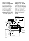
HIGH PASS
FILTER
FREQUENCY
SELECTION
MODULE
LOW PASS
FILTER
FREQUENCY
SELECTION
MODULE
C10
C13
JBL INC.
NORTHRIDGE, CA
JBL GTS600
PC00108800
REV A
CROSSOVER