


components is extremely
important for proper performance
and long term reliability.
All wiring connections should be
made either by soldering with
heatshrink tubing insulation or
with high quality crimp type
insulated connectors installed with
a good crimping tool. Soldering
crimp connections is recom-
mended to further enhance
connection reliability. Never use
wire-nuts, insulation-displacement
connectors (i.e. ScotchLok type), or
“twist and tape” connections. Do
not use electrical tape; it will
loosen with age and extreme
temperatures. Never leave bare
wire exposed.
Route the wiring through the car
carefully. Do not allow wires to lay
against sharp sheet metal edges or
any other surfaces that might wear
away or cut through the insulation
of the wire. Use insulated strain
reliefs, rubber grommets and
plastic tubing to protect the wires
whenever they are run through
sheet metal panels or are placed
where they might be pulled or
damaged.
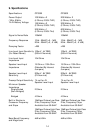
5
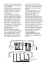
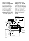
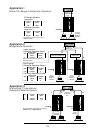
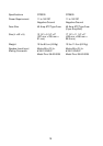
Cassette/CD Tuner
CD Player
or Changer
CD Input
Cassette/CD Preamp Output
Antenna Input
Power
Antenna
Power
Antenna
Relay
Blue w/White Stripe - Remote On/Off
Main +12V
Power Ground
Chassis Ground
Vehicle Battery
–
+
Ignition Switch
Antenna
Motor
Power
Supply
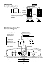
Blue (Blue/White)
Remote On/Off
Remote Antenna
Black - Power Ground
Red - Main +12V
Yellow - Back Up Power
Speakers
+
–
+
Fuse
Fuse
Fuse
Cassette/Receiver
Power Supply
Wires
GTS300 – 40 Amp
GTS600 – 80 Amp
(Not Included)
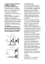
Amplifier
Power
Connection
Amplifier
Speaker
Output
Connection
Amplifier
Speaker
Level
Input
Line
Input
Cassette/CD Tuner
Speaker Level Output Connection
(Use only when line level ouput
is not available)
POWER
M
A
D
E
I
N
T
H
E
U
S
A