


6
The CS480 satellites and center channel are designed to be mounted
o
n the wall. There is a fixed-mount wall bracket and an adjustable
wall bracket provided for each satellite and the center channel. Each
s
peaker bracket will require up to four 1-1/2"#10
w
ood screws; each
screw should be fastened to a wall stud. If a wall stud is unavailable,
install an anchor appropriate for a 1-1/2"
#10 screw.
NOTE: The customer is responsible for the correct selection
and use of mounting hardware (available through hardware stores)
that will ensure the proper and safe wall-mounting of the speakers.
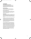
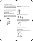
Fixed-Mount Wall Bracket
Step 1. Mark the positions on the wall where you would like to
p
lace the mounting screws.
Step 2. Attach the bracket to the wall using two screws
(not included).
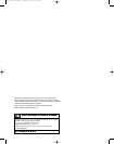
Step 3. Remove the rubber ring on the bottom of the satellite and
seat the satellite or center channel speaker onto the back bracket.
Step 4. Attach the 1/4-20 screw into the insert on the bottom of the
speaker and tighten.
A
djustable Wall Bracket
S
tep 1.
R
emove the cap over the threaded insert on the rear of the
speaker.
Step 2. Mark the positions on the wall where you would like to place
the mounting screws.
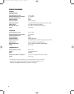
Step 3. Place the bracket against the wall and fasten four 1-1/2" #10
wood screws (not included) through the bracket’s screw holes into
the wall. If a wall stud is not available, use an appropriate anchor.
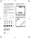
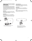
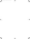
Step 4. Unscrew the round collar (C) from the bracket (A).
Step 5. Screw the ball and shaft assembly (B) to the 1/4"-20 insert on the
back of the satellite or the center channel (do not use the bottom insert
on either speaker). Back out 1/2 of a turn and tighten the nut against the
speaker. If the ball and shaft assembly is not backed out before tighten-
ing the nut, performing Step 8 below may dislodge the threaded insert in
the speaker housing and permanently damage the speaker.
Step 6. Attach the speaker wire as shown on page 7.
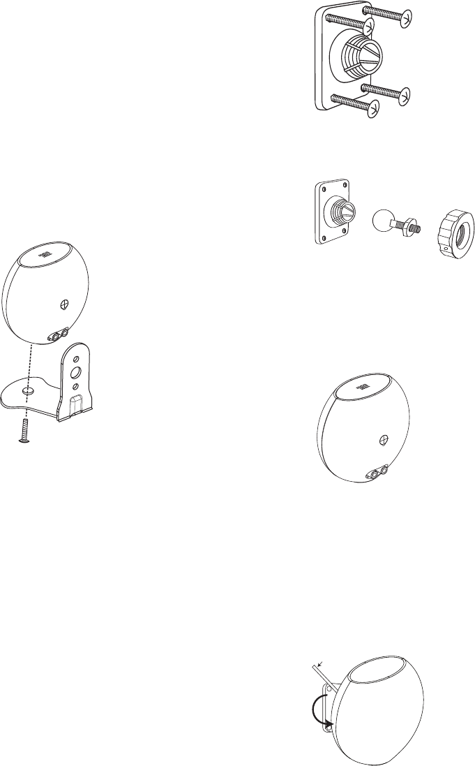
Step 7. Drop the round collar (C) over the ball and shaft assembly
(B) that is mounted to the speaker with the finished side of the collar
facing the rear of the speaker.
Step 8. Carefully push the ball straight into the socket mounted on the
wall, angle the speaker as desired and tighten the collar using the
enclosed metal bar.
Figure 3. Bracket on wall.
Metal bar
Metal bar
®
®
®
A
B
C
W
ALL
-
M
OUNTING THE SATELLITES
A
ND CENTER CHANNEL
CS 480-120V om.qxd 12/15/06 4:43 PM Page 8