


9
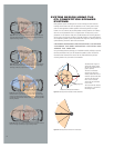
Figure 10.
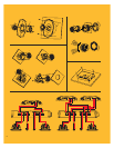
Figure 12.
1K 2K 5K 10K 20K
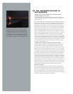
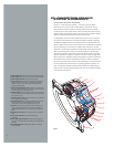
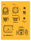
the tweeter’s output at low frequencies in the listening window and decreases its out-
put in the off-axis response. That’s a much closer match to the directivity of the woofer,
which is focused into the listening window in the crossover region. The crossover region
is also indicated in dark green in the frequency response plot in Figure 9.
At higher frequencies, the waveguide’s gentle curve (indicated in orange in Figure 9)
spreads the sound over all the angles, increasing the high-frequency content of the
off-axis response and decreasing it in the listening window. This region is also indicated
in light green in the frequency response plot in Figure 9. Essentially, the directivity of
the waveguide is the inverse of the tweeter’s directivity, and the combination of the two
provides nearly constant directivity over the tweeter’s range above the crossover. At the
highest frequencies (to the right of the orange region), the waveguide has no effect
because the dispersion pattern is narrower than the waveguide.
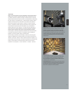
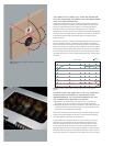
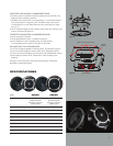
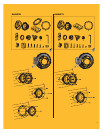
THE CROSSOVER: MORE THAN A DIVIDING NETWORK
The crossover included in GTi competition speaker systems is more than a set of
simple filters. The filter frequencies, slopes and Q values are carefully chosen to
provide a phase-aligned transition between woofer and tweeter with optimally
flat frequency response at the design axis and throughout the listening window.
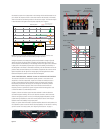
Additionally, the tweeter’s high-pass filter circuit includes a level control and
frequency contour to optimize the system’s response when the waveguide is used
or when the tweeter is conventionally mounted.
Capacitor, inductor and resistor types have been selected to minimize distortion
and maximize power handling. Air-core coils minimize saturation, which can cause
distortion at high input power. Low-loss, low-ESR polypropylene capacitors provide
crystal-clear high frequencies, while wire-wound precision resistors with integral
heatsink ensure filter stability at high input power.
Finally, for systems that will include a separate amplifier channel for each speaker, the
GTi competition system crossover includes bi-amp capability. For instructions in setting
up the crossover for bi-amp systems, see “Adjusting the Crossover” on page 11.
ENGLISH
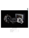
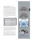
Figure 9. The waveguide provides a smooth and gradual increase in tweeter directivity in the
crossover region and a reduction in tweeter directivity at higher frequencies.
20 Hz 50 100 200 500 1K 2K 5K 10K 20K
dBSPL
-20
-15
-10
-5
0
5
10
15
20
Directivity Index
Sound Directed
Into Window
Sound Spread
Into Free Space
Sound Spread
Into Free Space
Sound Directed Into
Window
Tweeter Without Waveguide
Tweeter With Waveguide
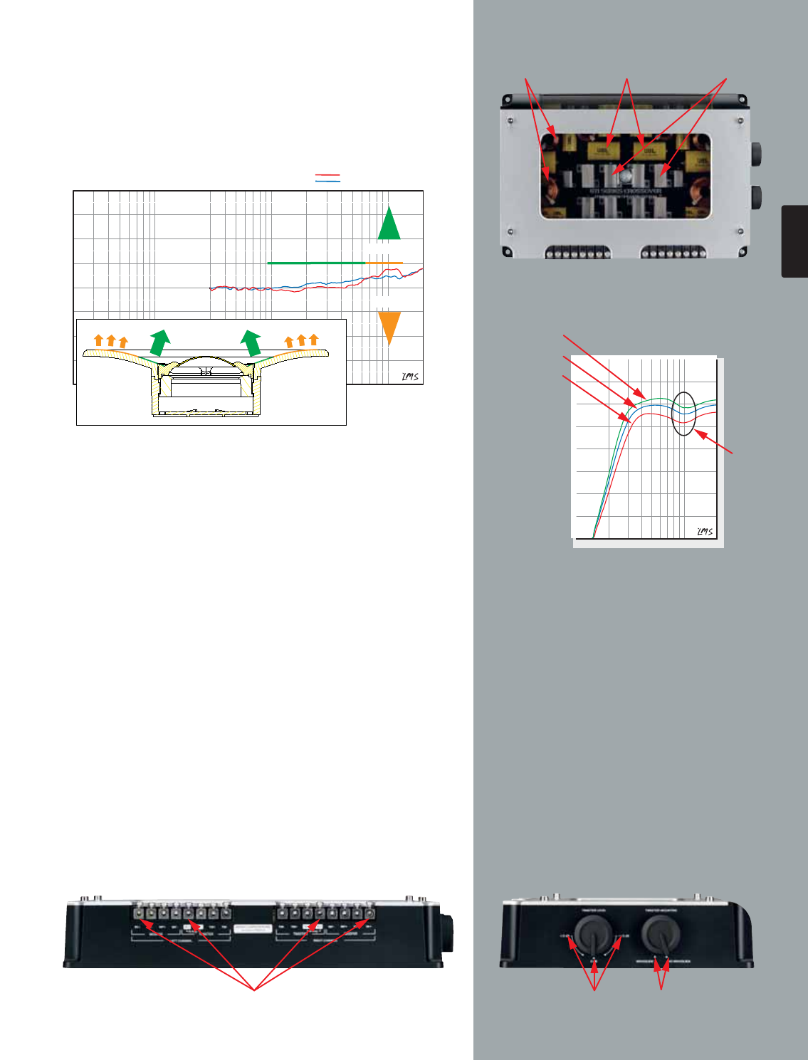
Figure 11.
Bi-Amp Capable Tweeter Level
Adjustment
Frequency
Contour
Air Core Coils
Polypropylene
Caps
Wire-Wound
Precision Resistors
With Integral Heatsink
Frequency
Contour
–1.5dB
0dB (Reference)
Tweeter Level Adjustment
+1.5dB