


CONTROL 328C/CT SYSTEM ASSEMBLY
7
JBL Professional Control 300 Series
Ceiling Preparation - Cut a 12.2 inch (310 mm)
diameter hole in the ceiling to allow sufficient room for the
loudspeaker baffle.
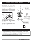
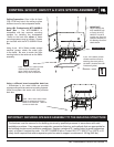
Assembling the Control 328C/CT into the Back Can
- After inserting the Control 328C/CT into the back can,
align the mouting holes without weld nuts to the holes with
clip nuts on the back can. These are the mounting points
that will be used to secure the Control 328 baffle and driver
to the backcan.
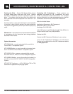
Next, using 4 pcs - #10 x 0.75 in (19 mm) sheet metal
screw, attaching the baffle / driver to the back can. Be
sure to match the mouting holes without weld nuts to clip
nuts on back can.
Finally, using 4 pcs - M4 x 38 mm powder coated machine
screws, attach the metal grille to the baffle. Be sure to
match the grille mouting holes to the weld nuts on the
baffle assembly.
4 pcs - #10 x 0.75 in (19 mm)
sheet metal screw for attaching
the baffle / driver to the back
can. Match to clip nuts on
back can. (Included with MTC-
300BB8. )
4 pcs - M4 x 38 mm powder
coated machine screws for
attaching the metal grille to
the baffle. (Included with JBL
Professional grilles.)
Weld nut
mount point
Non-Weld nut
mount point
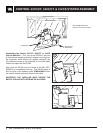
IMPORTANT!
When installing the
MTC-300BB8 with a
Control 328C/CT,
see “Securing Speaker
Assembly to the Building
Structure” details below.
The backcan must be secured to the building structure by qualified personnel in accordance with safe
installation practices. Use suspension materials, connection fixturing, and methods that are appropriate for
the building structure and installation conditions. Employ a minimum 5:1 safety factor for each suspension
point, or higher if required by code. For MTC-300BB8 with a Control 328C/CT a 5:1 safety factor requires
that each suspension point be rated to support a minimum of 57 kg (125 lbs).
IMPORTANT: SECURING SPEAKER ASSEMBLY TO THE BUILDING STRUCTURE