


5
JBL Professional Control 300 Series
WIRING INSTRUCTIONS
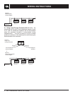
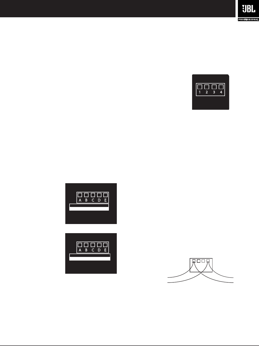
Guide to Connection Pins on Low Impedance Models
(Control 321C, 322C, 328C & 312CS) -- The removable
locking input connector contains 4 terminals, as marked on
the connector. The pin functions for the Control 328C, 328C
and 322C are listed on the label located on the crossover
frame and on the driver backplate on the Control 312CS.
Pins 1 & 4 are the “+” and “-” inputs to the loudspeaker.
Connect the negative wire to the “-” or pin 4 and connect the
positive wire to “+” or pin 1. Pins 1 & 4 are looped to pins 2 &
3, respectively (Pin 1 connects to Pin 2 and Pin 3 connects
to Pin 4) inside the speaker. Pins 2 & 3 are intended as loop-
through connections to subsequent loudspeakers. There are
two possible hookup schemes for connecting subsequent
speakers, determined by the desired result from the circuit
whenever this speaker’s connector gets disconnected during
troubleshooting.
Hookup Schemes for Subsequent Speakers
Choose whichever of the following hookup patterns best
accommodates your installation.
1.) Paralleling Input Terminals -- Connect the wire pair of
the subsequent speaker to pins 1 & 4 (in parallel with the
input wire pair). Whenever the connector is pulled out of the
speaker for troubleshooting, subsequent speakers will stay
connected. This can be useful during troubleshooting to be
able to disconnect a single loudspeaker at a time. In this
hookup scheme, no wires get connected to pins 2 & 3.
A
D
C
B
E
INPUT CONNECTION FROM
70V/100V AMPLIFIER LINE
Com
30W15W
7.5W
60W
70V
Com
60W
30W15W
N/C
100V
BLACK
ORANGE
PURPLE
BLUE
WHITE
A
D
C
B
E
INPUT CONNECTION FROM
70V/100V AMPLIFIER LINE
Com
50W25W
12.5W
100W
70V
Com
100W
50W25W
N/C
100V
BLACK
ORANGE
PURPLE
BLUE
WHITE
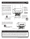
Control 321CT & 328CT:
Control 322CT:
+
-
1 432
Loop
Thru
IN
IN
+
-
Loop
Thru
CONNECTION
Control 328C, 321C,
322C & 312CS:
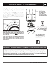
Control 300 Series Loudspeakers include Euroblock or
Phoenix-type locking input connectors that allow the system
to be “pre-wired” before the speakers are installed into their
respective back cans and backboxes.
Connecting the Wiring to the Euroblock -- Connect the
wiring to the removable locking connector that is INCLUDED
with the speaker by stripping the insulation back about 5
mm (about 3/16 inch), inserting the bare end of wire into
the connector and screwing down the hold-down screw until
tight using a small flatblade screwdriver. Tighten any unused
screws to avoid vibration. Using terminal block connectors
allows the system to be pre-wired before final installation of
the drivers.
When wiring Control 300 Series loudspeakers,
always use proper electrical wiring practices
in accordance with your area’s building codes
and regulations.
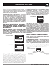
Guide to Connection Pins on Transformer Models
(Control 328CT, 321CT & 322CT) -- The removable locking
input connector contains 5 terminals, as marked on the
connector. The pin functions are listed on the label located
on the crossover frame.
For Control 328CT, 321CT and Control 322CT (transformer
models), connect the negative input to the “Common” terminal
and connect the positive input to the appropriate tap. For
example, if the system is being driven from a 70V Distributed
Line and in the case of the Control 321CT the 30W tap is
desired, the positive input would be made to the input marked
30W and the negative connection would be made to the
“Common” pin. The input pins correspond to the taps of the
transformer indicated on the label below each connector.
From Amplifier or
Previous Speaker
To Subsequent
Speakers
+
IN
1 2
-
Loop
Thru
+
-
+
3 4
-
IN
Loop
Thru
+
-
Figure A:
Paralleling Input Terminals