


8
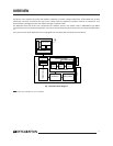
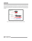
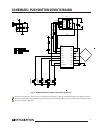
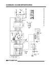
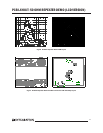
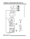
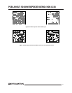
Fig 4. IA4220 434 MHz Push Button Transmitter Schematic
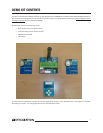
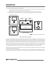
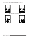
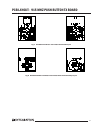
Antenna configuration, along with the configuration/frequency setting commands denote operating frequency.
Examples of the physical board differences can be seen on the following pages. It can be noted from these layouts that
only the antenna is different.
Array
EEPROM
XTL
SDI
1
SCK
2
SEL
3
WS1
4
WS2
5
WS3
6
WS4
7
CLK/SDO
8
XTL
9
VSS
10
MOD
11
RFN
12
RFP
13
IRQ
14
VDD
15
FSK
16
IC1
84
CS\
1
SO
2
HOLD\
7
SCK
6
SI
5
WP\
3
VCC
GND
IC2
C1
C2 C3
R1
D1
R2
R3
R4
R5
+-
B1
LED
31
24
S1
31
24
S2
31
24
S3
31
24
S4
1
2
3
SW1
1
SI
SCK
CS
SO
10 MHz
GND
VCC
VCC
VCC
GND
GND
GND
10u
100p 100n
470
10 k
3k3
3k3
6k8
SMDRET
SMDRET
SMDRET
SMDRET
SCHEMATIC: PUSH BUTTON DEMO TX BOARD