10
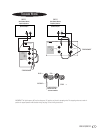
CAS 3.1/CAS 2.1
Right
Speaker
Receiver/
Amplifier
Right
Left
HF –
HF+
LF –
LF+
Left
Speaker
HF –
HF+
LF –
LF+
–
+
CAS 2.1
Right
Speaker
Amplifier 1
Right
Left
HF –
HF+
LF –
LF+
Left
Speaker
HF –
HF+
LF –
LF+
–
+
Amplifier 2
Right
Left
–
+
CAS 2.1
Single-Stereo Amplifier
Dual-Stereo Amplifier
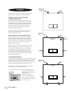
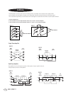
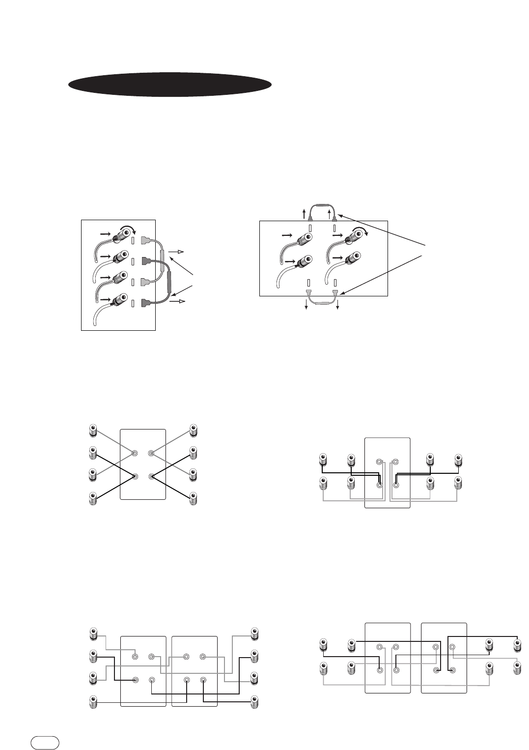
BI-WIRING
The CAS speaker’s connection panel and internal dividing network are designed so that separate sets of speaker cables
can be attached to the low-frequency transducer and midrange/high-frequency transducer portions of this dividing network.
This is called bi-wiring. Bi-wiring can provide several sonic advantages and considerably more flexibility in power amplifier selection.
1. Remove strapping wires.
2. Insert the speaker wire for the high frequencies into the (HF+) and (HF–) terminals and tighten.
3. Insert the speaker wire for the low frequencies into the (LF+) and (LF–) set of terminals and tighten.
HF –
HF+
LF –
LF+
HF+
HF –
LF+
(–)(–)
(+) (+)
LF –
CAS 2.1
CAS 3.1
STRAPPING WIRES REMOVED
STRAPPING WIRES REMOVED
–
+
–
+
Right
Speaker
Amplifier 1
Right
Left
LF+
LF –
Left
Speaker
HF+
HF –
LF+
LF –
HF+
HF –
CAS 3.1
–
+
Amplifier 2
Right
Left
–
+
–
+
Right
Speaker
Receiver/
Amplifier
Right
Left
LF+
LF –
Left
Speaker
HF+
HF –
LF+
LF –
HF+
HF –
CAS 3.1
One amplifier drives the low-frequency sections of both speakers.A second amplifier drives the
mid/high-frequency sections of both speakers.
STRAPPING WIRES REMOVED
STRAPPING WIRES REMOVED


