


BassLink/BassLink X
8
Equipment needed:
• Function/signal generator/sweep generator
• Integrated/Power Amplifier (capable of driving 2 ohm loads)
• 14 volt DC power supply 20A or greater with current-limit protection
• Multimeter
• RCA cable, Universal Interface molex connector, Speaker cables
General Unit Function (UUT = Unit Under Test)
Switch/Controls:
GAIN control full counterclockwise (Min)
CROSSOVER full clockwise (120 Hz)
BASS BOOST at center (12 o’clock)
PHASE, AUTO-ON - either position
1) From the signal generator, connect one line level (RCA) cable to the Basslink Line Level Input jacks (Front,L/R) on the UUT. Use
a Y-cable from a mono source if necessary to connect to both inputs.
2) Turn on generator, adjust to 100mV, 40 Hz.
3) Attach 14v DC source to Power terminals on UUT, including +14v to Remote connection. Red LED should ON. Turn LEVEL con-
trol full clockwise (Max)
4) Bass response should be heard and felt. Green servo light should not be illuminated.
5) Adjust the generator to 175mV, 40 Hz. Green servo light should turn ON. DO NOT DRIVE THE BASSLINK FOR MORE THAN A
FEW SECONDS AT THIS LEVEL OR THE UUT MAY GO INTO THERMAL PROTECTION
6) Turn off generator, turn GAIN control fully counterclockwise, disconnect RCA cable.
7) Optional: Attach the Universal Interface molex connector (Infinity part# 162A600D001) to the Basslink Universal Interface Jack
(Front,L/R) on the UUT. Both front/rear negative wires should be twisted and connected together; positive wires should be treated
likewise. Cables should be connected to an integrated amplifier fed by the signal generator.
8) Turn on generator and adjust so that speaker level input at the amplifier is 275mV, 40 Hz. Turn GAIN control full clockwise.
9) Bass response should be heard and felt. Green servo light should not be illuminated.
10) Adjust the generator to 500mV, 40 Hz. Green servo light should be ON. DO NOT DRIVE THE BASSLINK FOR MORE THAN A
FEW SECONDS AT THIS LEVEL OR THE UUT MAY GO INTO THERMAL PROTECTION
Sweep Function
1) Follow steps 1-3 above, using a sweep generator as a signal source – adjust the generator to 50mV, 40 Hz.
2) Sweep generator from 20Hz to 300Hz. Listen for any rattles, clicks, buzzes or any other noises. If any unusual noises are heard,
test woofer according to the instructions below.
Driver Function
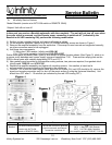
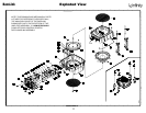
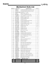
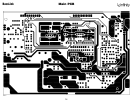
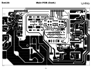
1) Remove amplifier from the enclosure; (instructions in bulletin INF2000-03 page 8); detach connector M101 two-wire molex on the
main amplifier PCB.
2) Check DC resistance of woofer; it should be 2.3 ohms ±10%
3) Connect a pair of speaker cables to woofer terminals. Cables should be connected to an integrated amplifier fed by a signal gen-
erator. Turn on generator and adjust so that speaker level output is 6.0V.
4) Sweep generator from 20Hz to 1kHz. Listen to driver for any rubbing, buzzing, or other unusual noises.
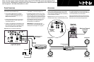
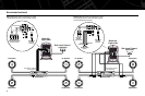
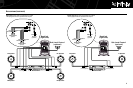
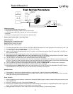
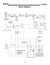
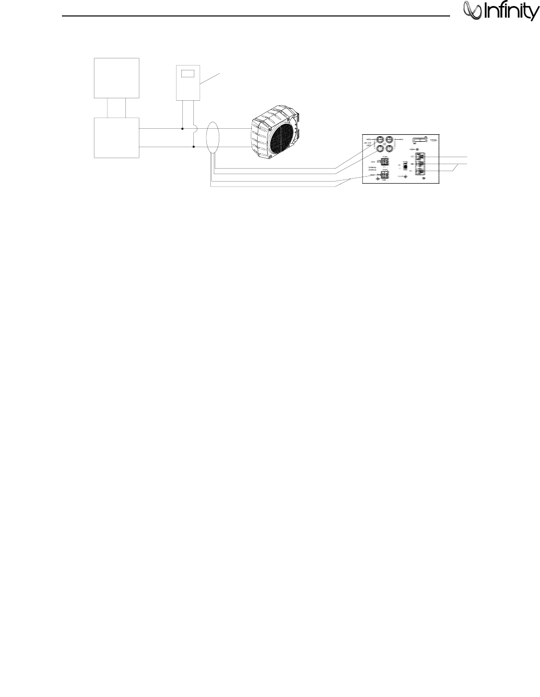
SIGNAL
GENERATOR
AMPLIFIER
AC VOLT
METER (10V)
BASSLINK
UNDER TEST
00432
-
+
14V DC
Test Set Up Procedure