


4
NOTE: When using the Hi-level inputs, connect
the REMOTE terminal to the source unit.
REMOTE OUT
If using additional amplifiers and tower speakers
connect the REMOTE OUT terminal using a 1/4"
spade connection to the Remote input terminal
of the other amplifier. The REMOTE OUT works
in conjuction with the Power switch on the
microphone (please refer to page 5).
LINE IN
Connect to the source unit’s line-level output
using RCA cables.
LINE OUT
Can be used to pass signal from the Line In to
additional amplifiers. Also has the option to pass
paging information (refer to Page Ext switch).
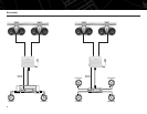
SPEAKER CONNECTIONS
Refer to the application guides on the pages
that follow. Speaker connections should be
made using the supplied speaker wires. If
additional wire is necessary, use a minimum
of 16 awg. speaker wire.
Minimum speaker impedances:
6100m amplifier 4 ohms, stereo
2100m amplifer 2 ohms, stereo/4 ohms, bridged
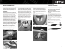
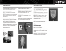
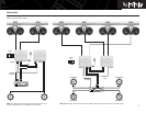
HI-LEVEL INPUT CONNECTIONS
The 6100m and 2100m amplifiers are equipped
with speaker-level inputs that allow you to add
an amplifier to head units that do not have RCA
line outputs. The speaker outputs for the source
unit should be connected to the amplifier using
the supplied connector (square four-wire plug).
Remember to check for proper polarity.
Figure 7. Speaker-level connector.
NOTE: When using the Hi-level inputs, the
Line Out on the 6100m can be used to pass a
full-range line-level signal to another amplifier.
Mount the 6100m or 2100m amplifier in a
location that is away from direct contact with
water, whether from washing, big waves or
soggy riders.
Choose a location in the boat where the
amplifier will not be damaged by shifting cargo
or passengers. If the amplifier is going to be
under a seat, ensure that it is clear of all moving
parts and will not affect the seat adjustments.
If mounting the amplifier in an enclosed space,
make sure there is plenty of air circulation for
the amplifier to cool properly.
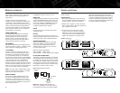
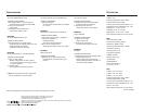
POWER CONNECTIONS
The 6100m/2100m amplifiers are capable of
delivering high power levels, and require a
reliable connection to the boat’s electrical
system in order to perform optimally. See
Figure 8 for terminal location. Please adhere
to the following instructions carefully:
GND TERMINAL
Connect the amplifier’s Ground (GND) terminal
directly to the boat’s negative (–) battery terminal
using a minimum of 8-gauge power wire.
+12V TERMINAL
Connect a minimum of 8-gauge power wire
directly to the boat’s positive battery terminal,
and install an appropriate fuse holder within
18" of the battery terminal. Do not install the
fuse at this time. Route the wire to the amplifier’s
location, and connect it to the amplifier’s positive
(+12V) terminal. Be sure to use appropriate
grommets whenever routing wires through
panels. Failure to adequately protect the positive
wire from potential damage may result in a fire.
When you are done routing and connecting this
wire, you may install the fuse at the battery.
NOTE: If your boat uses a multiple battery setup,
please contact the boat manufacturer or dealer
for proper connection instructions.
REMOTE TERMINAL
Connect the amplifier’s REMOTE terminal to
the source unit’
s R
emote Turn-On lead, using
a minimum of 1
8-g
auge wire. If your source
unit does not have a remote turn-on connection,
connect the amplifier
’s REMOTE terminal to the
boat’
s accessory circuit.
PAGE EXT SWITCH
When set to the ON position, the Page Ext
switch will allow the PA signal to pass through
to another amplifier when using the Line Out
outputs on the 6100m amplifier. Set to OFF if
you do not want the PA signal to pass through
to another amplifier and speakers.
Setting the controls on the 6100m amplifier or
2100m amplifier.
SETTING THE GAIN
1. Start with the GAIN control set to minimum
(counterclockwise) and set the music level on
the microphone to maximum (clockwise).
2. Reconnect the negative (–) lead to the boat’s
battery. Apply power to the audio system and
play a dynamic music track.
3. On the source unit, increase the volume
control to 3/4 volume. Slowly increase the
GAIN control until you hear slight distortion
in the music. Then reduce the GAIN control
slightly until distortion is no longer heard.
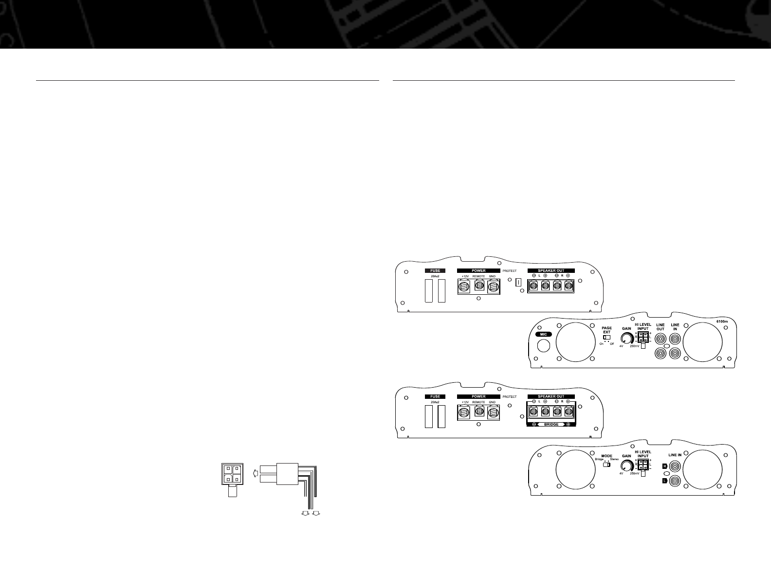
Figure 8. End plates.
CONTROLS AND SETTINGSMOUNTING THE AMPLIFIER
REMOTE
OUT
R
L
2100m
HIGH LEVEL
INPUT
Speaker Wires
(spliced)
RL
+
R
–
+
L
–
+ WHITE
– WHITE/BLACK
GRAY/BLACK –
GRAY +
6100m
2100m