


Owner’s Manual/Installation Guide – 7
4. Using the Weco 5-pin connector, connect a blue wire from
the source unit’s remote connection to the REM terminal.
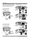
Depending on polarity requirements (see Figures 1
through 3 on pages 3 and 4), connect speaker wires from
the subwoofer(s) to the L and R (+ and –) terminals, as
required by your system plan.
5. Make sure the wires are firmly seated in the Weco 5-pin
connector and that each screw is completely tightened.
Insert the wired Weco 5-pin connector into the
SUBWOOFER socket (on the amplifier’s rear panel).
Press it in until it stops.
6. Using Weco 4-pin connectors, connect speaker wires from
the front and rear speakers to the amplifier. Depending
on your system plan (see Figures 1 through 3 on pages 3
and 4), match the polarities on the L and R (+ and –)
terminals.
NOTE: In 3-way applications, the rear amplifier provides
bandpass channels to drive midrange or midbass speakers.
7. Make sure the wires are firmly seated in each Weco 4-
pin connector and that each screw is completely tightened.
Insert the wired Weco 4-pin connectors into the FRONT
and REAR sockets (on the amplifier’s front panel). Press
each one in until it stops.
8. Connect RCA cables from a source unit to the L /R,
FRONT/REAR INPUT jacks. If the source unit has
subwoofer outputs, also connect a pair of RCA cables from
those jacks to the SUB INPUT jacks and set the SUB
INPUT switch to EXT (see Figure 7).
S ETTING THE CROSSOVERS...
1. To use the Kappa 255a in a front/rear system, set the
CROSSOVER controls to frequencies recommended by
the speaker manufacturer (see Figure 7). If the value is
unknown, set the control midway.
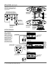
2. For a 3-way system, set the OUTPUT and REAR INPUT
switches to create the appropriate bandpass filters (see
Figures 2 and 3 on pages 3 and 4).
S ETTING INPUT SENSITIVITY...
Initially, turn the front and rear input sensitivity GAIN
controls to their minimum (counter-clockwise) positions
(refer to Figure 7).
1. Reconnect the (–) negative lead to your vehicle’s battery.
Apply power to the audio system and play a favorite
music track from CD or tape.
NOTE: After the source unit is on, green LEDs (on the top
panel) will illuminate, indicating the amplifier is on. If not,
check the wiring, especially the remote connection from the
source unit. Also refer to “Troubleshooting” on the next page.
2. On the source unit, increase the volume control to
maximum position. Slowly increase the Front and Rear
GAIN controls (clockwise) towards three o’ clock and, at
the same time, listen to the quality of the reproduced
sound. At some point, you’ll hear distortion on the music
peaks. Stop the adjustment and turn it back slightly.
S ETTING DBO...
Dynamic Bass Optimizer (DBO) is a new approach to
enhancing low-frequency reproduction in a vehicle.
Conventional bass boost controls add bass at a fixed
frequency and cause the amplifier to consume considerable
power. DBO conserves valuable power at the lowest
frequencies and allows you to adjust the level and
“character” of the bass sound, instead of just the amount of
boom.
Since a subwoofer in a tuned box is given to overexcursion
below the tuned frequency, set the FREQ control below the
box’s resonant (tuned) frequency (see Figure 8 on the next
page). Power typically wasted in this region will now be
conserved and instead be available for frequencies the
enclosure will reproduce. Use the Q control to boost the
bass at the set frequency by as much as 12 dB (at MAX
position – see Figure 8 on the next page).
For sealed enclosures, use DBO to enhance the output so it
sounds more like a tuned box. This is a result of 12 dB of
rolloff being added to the enclosure’s rolloff and a flattening
of frequency response (at the curve’s knee) when Q is
boosted.
For infinite baffles, set the FREQ control to the speaker’s
F
s
value (to keep the subwoofer from trying to create bass
below the resonant frequency) and adjust the Q control
according to personal taste.
I NSTALLING THE CONTROL COVER...
After wiring and testing the Kappa 255a amplifier, install
the control cover using the enclosed machine screws to
deter tampering and help seal out dust.
NOTE: Do not over-tighten the machine screws. Doing so may
crack the cover.
ST
BR
HP
FLAT
LP
.25V
9V
G
A
I
N
G
A
I
N
G
A
I
N
M
O
D
E
M
O
D
E
O
U
T
P
U
T
C
R
O
S
S
O
V
E
R
.25V
9V
.25V
9V
80Hz
20Hz
320Hz
32Hz
60
Hz
Q
FREQ
REAR
INPUT
SUB
INPUT
MIN
MAX
320Hz
32Hz
320Hz
32Hz
HP
FLAT
LP
FRONT LP
EXT
INT
EXT
ST
BR
SUBWOOFER
FRONT REAR
50W X 4
+
200W CLASS D
DIGITAL SUBWOOFER
AMPLIFIER
O
U
T
P
U
T
C
R
O
S
S
O
V
E
R
D
B
O
X
O
V
E
R
x1
x15
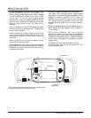
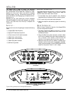
INSTALLATION (continued)
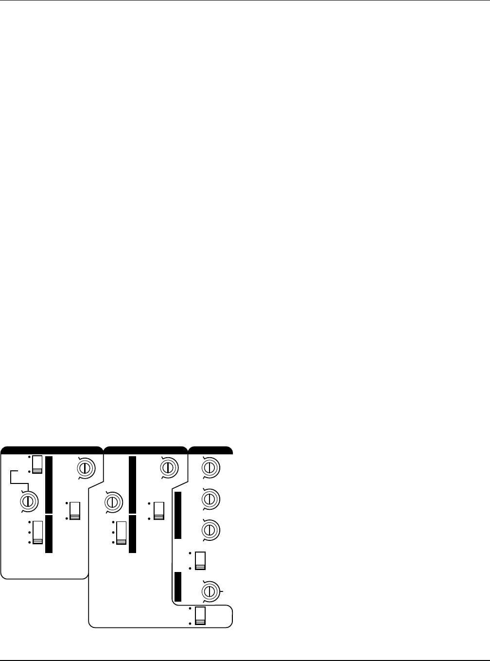
Figure 7. Kappa 255a controls for crossover, input, output, and
DBO (Dynamic Bass Optimizer).