5
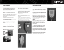
MOUNTING THE MICROPHONE CONNECTOR PLATE
Locate a suitable place for the microphone plate
to be installed. (Make sure that there are no
wires or control lines behind this surface.)
Mark the four screw locations.
Draw an “X” between the mounting screw
locations.
Using a 7/8" holesaw, drill a hole in the center of
the “X” to allow the microphone cable to be
passed through.
Pre-drill the mounting screw locations.
Route the microphone cable from the amplifier
to the plate mounting location.
Pass the cable through the hole and secure
to the plate using the supplied lock ring and
ring tool.
Position the assembled plate over the mounting
hole and secure, using the supplied screws.
Connect the microphone and install the
weather-resistant cover.
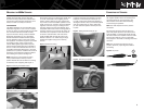
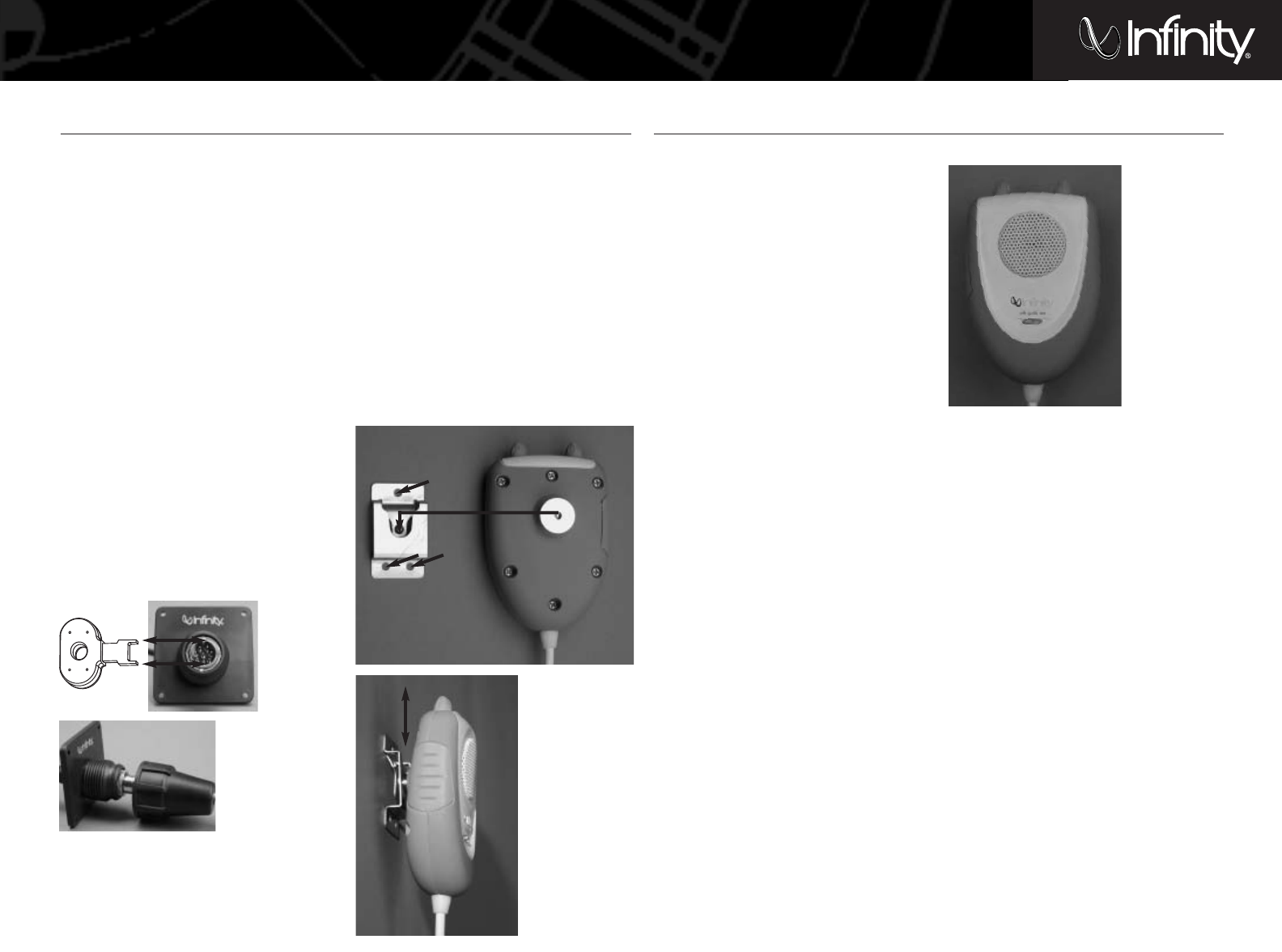
Figure 9. Mounting the connector plate.
POWER SWITCH
OFF – Turns the 6100 system off.
AUTO – Allows the 6100m system to operate in
conjunction with the REMOTE trigger from your
head unit.
ON – Turns the 6100m system ON; allows the PA
feature to be used without having to turn the
audio system on.
NOTE: When you’ve finished using the system,
make sure the Power switch is placed in the
AUTO or OFF position. If the system is left in the
ON position for an extended period of time, it
may deplete the battery.
CONTROLS
Music level – Adjusts the volume of the music
that is played through the 6100m system.
Page level – Adjusts the volume level of the
paging system.
OPERATIONS AND WARNINGS
To operate the microphone, push in and hold
the MIC button while speaking. Release the
button once you are finished.
Hold the microphone approximately 3– 6 inches
from your mouth. Refrain from shouting into the
microphone; this can cause distortion at higher
volumes.
If you hear feedback (squeal) while using the
Page system, move the microphone away from
your mouth and/or reduce the page level.
MOUNTING THE MICROPHONE HOLDER
Locate a position to secure the microphone
holder and mark screw hole positions.
NOTE: This location should be within reach of the
driver but should not hinder any of the normal
operations of the boat or safety equipment
(lights, steering, throttle control, etc.).
Predrill the holes.
Using three of the supplied screws, mount
the holder.
Align the ring on the back of the microphone
with the holder and slide in a downward motion.
The microphone will click into the holder.
Figure 10. Mounting the microphone holder.
6100M MICROPHONE
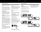
Figure 11. Microphone.
MICROPHONE OPERATION


