


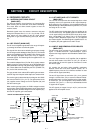
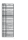
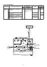
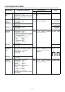
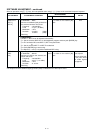

CPU-Continued
4 - 5
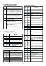
Outputs control signal for the power
switching circuit (MAIN unit; Q24,
Q23).
Outputs IF bandwidth control signal.
Low : While IF bandwidth is narrow.
Outputs control signal for the AF mute
circuit (MAIN unit; Q35, Q36, D29).
High: While AF amplifier (MAIN unit;
IC8) is activated.
I/O ports for the optional board control
signals.
Outputs BUSY detection signal for the
optional board via MAIN unit, J1.
Input port for the clock signal from the
optional board via MAIN unit, J1.
Input port for the cloning signal.
Output port for the cloning signal.
Input for the POWER switch.
Input port for the remote power control
signal from external connector (MAIN
unit; J6).
Input port for the “NOIS” signal which
ºis used noise squelch operation from
the FM IF IC (MAIN unit; IC1).
Input port for the interruption signal
from the optional board via MAIN unit,
J1.
Outputs the chip select signal for the
optional board via MAIN unit, J1.
Input port for the PTT switch from
microphone.
Input port for the PTT switch from the
external connector (MAIN unit; J6).
Low : External PTT switch is ON.
Input port for the microphone hanger
detection signal.
Low ; Microphone on hook.
Input port for the AF volume control
(FRONT unit; R14).
High: [VOL] is maximum clockwise.
Input port for CTCSS/DTCS decoding
signals.
Input port for the single tone decoding
signals.
Input port for the optional board detec-
tion signal.
Input port for the detection signal of the
received signal strength.
Input port for the PLL lock voltage.
41
42
43
44–46
47
48
49
50
51
52
53
54
55
56
57
58
59
60
61
62
63
64
PWON
NWC
AFON
OPT3–
OPT1
BUSY
SI
CLI
CLO
POSW
IGSW
NOIS
CIRQ
CCS
PTT
EPTT
HANG
AFVI
CDEC
SDEC
OPV1V2
RSSI
LVIN
Pin Port
Description
number name