


4
2
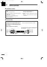
INSTALLATIONS
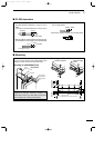
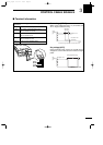
■ PL-259 connector
q Slide the coupling ring over the coaxial cable. Strip
the cable jacket and pull back to reveal 10 mm of
braid.
•
Soft solder the exposed braid and then pull out the jacket.
w Strip the cable as shown below. Soft solder the cen-
ter conductor the entire length of the exposed braid.
e Slide the connector body over the cable and sol-
der as shown below.
r Screw the coupling ring onto the connector body.
Solder
Solder
1–2 mm
10 mm
soft solder
10 mm
3
⁄8 inches
Coupling
30 mm
10 mm (soft solder)
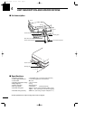
■ Mounting
Attach the AT-141 either horizontally or vertically with
one of the water drains facing downwards. After
mounting, remove the screw in the water drain.
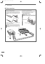
Mounting on a Mast/Metal pole
Mounting on a flat surface
Nut
Spring
washer
Flat
washer(L)
Flat
washer(L)
Hex head
bolt
Drill a hole here
Diameter:7–8 mm;
9
⁄32–
5
⁄16 inches
Weatherproof cap
Flat
washer(S)
Using self-tapping
screws
Using nuts and bolts
WARNING: Mount the AT-141 securely with the
supplied nuts and bolts. Otherwise, vibrations and
shocks due to waves, etc. could loosen the antenna
tuner making if fall, causing personal injury.
Using U-bolts
U-bolt
U-bolt plate
Flat washer(L)
Spring washer
Nut
Mast/
Metal pole
Flat washer(S)
AT-141_0.qxd 05.12.1 11:06 Page 4