


2
1
ANTENNA SYSTEM
■ Coaxial cable
Insulate the lead-in cable of the AT-141 antenna ter-
minal and antenna element from other metal objects.
To prevent interference, keep cables as far as possi-
ble from an antenna, electric pump and other elec-
tronic equipment.
To prevent erroneous indications, keep cables as far
away as possible from the flux gate compass.
Use suitable noise filters for alternators, fluorescent
lights, etc. Ask your Dealer for details.
■ Ground and counterpoise
Why a ship’s ground is required
The AT-141’s ground terminal MUST be connected
to your ship’s ground. Grounding prevents electric
shocks, interference to other equipment and other
problems. Grounding also ensures effective signal
transmission.
DANGER! NEVER connect the ground terminal to
the following points. These connections may cause
an explosion or electric shocks:
– Gas or electrical pipe
– Fuel tank or oil-catch pan
IMPORTANT! The mounting plate is NOT con-
nected to the AT-141’s internal ground.
Ideal ground points
One of following points is ideal:
– External ground plate
– External copper screen
– External copper foil
Good ground points
If electrically connected to sea water, one of the fol-
lowing points is usable:
– Stainless steel stanchion
– Through mast
– Through hull
– Metal water tank
Undesirable ground points
AVOID the following points, if possible. These con-
nections may cause noise or electrolysis:
– Engine block
– Ship’s DC battery ground
Electrolysis
All ground cables from the AT-141, HF transceiver,
etc. on your ship should be connected to only 1 ship’s
ground.
AVOID connection to 2 or more points. Voltage dif-
ference between 2 or more ship’s grounds may cause
electrolysis.
AVOID connection between dissimilar metals where
an electric current is present. These connections may
cause electrolysis.
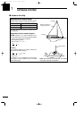
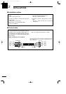
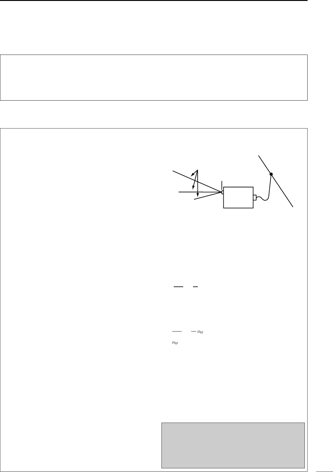
Counterpoise
If your ship is made of FRP, etc. and a good ship’s
ground is not available, connect a counterpoise.
1
⁄4λ (quarter wavelength) radial for each band is suit-
able for a counterpoise. Install the counterpoise di-
rectly below the AT-141’s ground terminal. Insulate
the ends of each radial from other metal objects. Lay-
out the radial horizontally and as straight as possible.
L : Counterpoise length for the operating frequency [m]
f : Operating frequency [MHz]
[Example]
At an operating frequency of 16 MHz, use a counter-
poise with the following length:
Ground cable
For best results, use the heaviest gauge wire or metal
strap available. Make the distance between the AT-
141’s ground terminal and ship’s ground as short as
possible.
Supplied ground cable can be used for ground con-
nection to a through mast. Confirm that the through
mast is electrically connected to sea water.
R WARNING!— When grounding to metal hull
Use a Zinc anode to protect the hull from
electroly-
sis.
Ask your technical dealer, installer or refer to a tech-
nical book, etc., for RF ground details.
L =
300
16
×
1
4
4.7 [m]
1 m
39 inches
L =
300
f
×
1
4
Ground terminal
AT-141
1
⁄4λ radial for
each band
AT-141_0.qxd 05.12.1 11:06 Page 2