


Pub. 42004-615L2
Model 670-801-EX and 670-801-UL SmartSeries Amplifiers Page: 8 of 15
\\s_eng\gtcproddocs\standard ioms - current release\42004 instr. manuals\42004-615l2.doc
6/97
UL Version
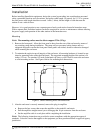
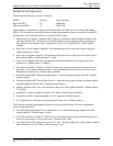
1. Install the conduits for system and speaker cable and make connection to the enclosure. External
conduits in Class I, Groups C, and D must have gas seals located not more than 18 inches (457mm)
from the amplifier enclosure. External conduits in Class II and Class III areas must also have seals if
the conduit is not dust-tight.
2. Feed the wiring through the conduit and into the enclosure.
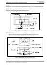
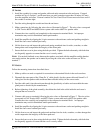
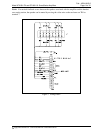
3. Make connections by following the wire colors as illustrated in Figure 7. The wire colors correspond
to GAI-Tronics 60029 and 60038 Series system cable and to 60021 for speaker cable.
4. Connect the wires carefully and completely to the compression terminal block. An improper
termination may result in diminished station performance.
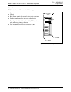
5. Install the amplifier by aligning the 16-pin connector to the enclosure socket and pushing straight in.
Install the four screws retained previously.
6. Lift the front cover and inspect the gasket and mating machined rims for nicks, scratches, or other
damage that could compromise the integrity of the flame path.
7. Secure the front cover in place using the bolts provided. Tighten the bolts alternately with bolts that
are diagonally opposite to ensure that the cover is evenly sealed.
N
OTE: If acoustical feedback occurs between the speaker associated with the amplifier and the handset
on a nearby station, the speaker can be muted by moving the violet wire on the enclosure on TB1 to
terminal 7.
EX Version
Follow the mounting instructions described above.
1. Make up cable core ends as required for connection to the terminal blocks in the enclosure base.
2. Dismantle the outer parts of the 25mm Ex ‘d’ cable gland(s) for the system cable and 16mm Ex ‘d’
cable gland for the speaker cable and thread them onto the cable(s) in the correct order.
3. Feed the cable end(s) into the enclosure through the gland body or bodies and reassemble the outer
gland parts as directed by the manufacturer.
4. Before tightening of the gland assembly, check that the slack in the cable inside the enclosure is
adequate but not excessive.
5. Connect cable cores to terminals following the wire colors as illustrated in Figure 7. The wire colors
correspond to GAI-Tronics 60071 and 60072 Series system cable and to 60070 for speaker cable.
Connect the wires carefully and completely to the compression terminal block. An improper
termination may result in diminished station performance.
6. Install the amplifier by aligning the 16-pin connector to the enclosure socket and pushing straight in.
Install the four screws retained previously.
7. Lift the front cover and inspect the gasket and machined rim for nicks, scratches, or other damage that
could compromise the integrity of the flame path seal.
8. Secure the front cover in place using the bolts provided. Tighten the bolts alternately with bolts that
are diagonally opposite to ensure that the cover is evenly sealed.