


28 GB4 User Guide
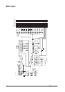
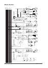
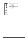
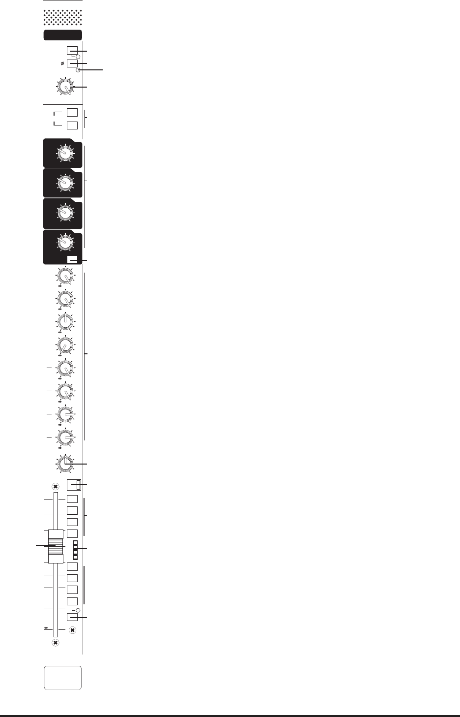
Stereo Input
STE MIC GAIN (1) adjusts the sensitivity of both pairs of Mic (XLRs) or Line (1/4" jacks) inputs.
Both pairs are electronically balanced, and are located on the rear connector panel.
The PEAK LED (2), monitors both left and right signals after the gain control.
The 48V switch (3) applies 48V phantom power to the input XLRs. An adjacent LED indicates
when the phantom power is on.
The Left PHASE switch (4) inverts the phase of the left channel.
The L switch (5) routes the left input signal to both L and R channels in the module. The R switch
similarly routes the right input signal. Pressing L and R together mono sums the input.
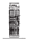
The EQ section (6) is four band, with shelving high and low frequencies and peaking high-mid
and low-mid bands.
The HF control gives +/-15dB cut/boost at 12KHz. The LF control gives +/-15dB cut/boost at
60Hz. The HM control gives +/-15dB cut/boost at a centre frequency of 2.5kHz, and the LM
control gives +/-15dB cut/boost at a centre frequency of 450Hz.
The EQ is switched in by the EQ switch (7).
A mono sum of the signal is sent to the AUX 1-8 busses via individual level pots (8). Aux 1- 4 are
pre fader signals, whilst Aux 5-8 are globally selectable pre or post fade via switches on the
master section.
The BAL control (9) allows the stereo image to be balanced between the left and right channels
within the module.
The stereo signal in the module is turned on and off by the illuminated MUTE switch (10), and
also the master mutes M1-M4 from the master section, if they are selected using the M1 - M4
switches (11).
Post-fader signal level is controlled by a 100mm stereo fader (12).
The signal is sent to the stereo mix bus, centre bus and 4 group busses using the C, L+R, 1-2
and 3-4 switches (13). Note the use of group 1 & 2, and group 3 & 4 as 2 sets of stereo pairs.
The feed to the centre bus is a mono sum of the stereo signal.
A 4-segment LED bargraph meter (14), next to the fader, meters the signal post-EQ, pre-mute,
pre-fade. The meter has a peak type response.
The PFL switch (15) feeds a mono sum of the pre-mute, pre-fade signal to the monitor output
and phones output. An adjacent LED indicates when the PFL is on.
60dB
30
5
GAIN
MIC
STE
48V
PK
LINE
-20
=
HF
HM
LM
LF
15
12
9
6
33
6
9
12
15
-
+
0
15
12
9
6
33
6
9
12
15
-
+
0
15
12
9
6
33
6
9
12
15
-
+
0
15
12
9
6
33
6
9
12
15
-
+
0
EQ
10
5
0
5
10
15
20
30
+16
+8
0
-10
M
1
M
2
M
3
M
4
C
1
2
L
R
3
4
PFL
L
R
MONO
L
6
0
+
6
0
+
6
0
+
6
0
+
6
0
+
6
0
+
6
0
+
6
0
+
AUX1
AUX2
AUX3
AUX4
AUX5
AUX6
AUX7
AUX8
BAL
PRE
PRE
PRE
PRE
POST
POST
POST
POST
PRE
PRE
PRE
PRE
R
L
0
MUTE
STE1
STE1
1
3
4
5
6
7
15
10
11
8
12
13
9
14
2