


31GB4 User Guide
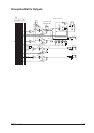
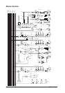
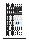
Master Section
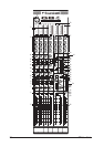
GROUPS
Note that the group controls are swappable with the aux 1-4 controls by pressing the GRP/AUX
SWAP switches (1). If the contols are swapped the aux and group faders swap function (and
their respective AFL buttons) and the group insert point becomes an aux insert point. The 12-
segment meter swaps function.The group and aux output connectors retain their original function.
The following description assumes that swap mode is NOT used.
The GRPx fader (2) controls the level after the insert point. This signal is fed to the Group Output
XLR on the rear connector panel.
The 12-segment meter (3) monitors the level after the fader.
The AFL button (4) feeds the group post-fader signal to the monitor output and phones output.
The post-fader signal is routed to the main mix stereo pair via the L-R switch (5) and the centre
mix via the C switch (6). The Group PAN pot (7) is before the L-R switch in the signal path. It is
used to position the group’s signal within the stereo image of the main mix.
The post-fader signal may be routed to any or all of the 4 matrix busses via the four matrix input
pots (8).
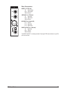
AUX MASTERS 1-4
Aux masters 1-4 are all pre-fade feeds from the input modules.
Each AUX master 1-4 level pot (9) controls the level fed from its own aux bus to its aux output.
The AFL button (10) feeds the aux post-fader signal to the monitor output and phones output.
AUX MASTERS 5-8
Aux masters 5-8 are each globally selectable to be pre-fade or post-fade feeds. this is done via
the PRE (11) switch.
Each AUX master 5-8 level pot (12) controls the level fed from its own aux bus to its aux output.
The AFL button (13) feeds the aux post-fader signal to the monitor output and phones output.
MATRIX MASTERS
Each MTX MASTER level pot (14) controls the level fed from its own matrix bus to its matrix
output.
The AFL button (15) feeds the matrix master post-fader signal to the monitor output and phones
output.