


– 17 –
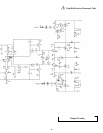
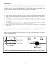
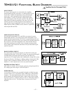
INPUT CIRCUIT
The stereo input signals are connected to the amplifier
through balanced XLR connectors, or unbalanced RCA con-
nector TP2. Unbalanced operation can be selected with
switch DS1, which grounds the RCA shell through R37.
Input buffers U1 and U10 provide a stable input imped-
ance, dominated by R10, R4, R42, and R32. The left and
right balanced summing amplifiers U4A and U3A sum the
inverting and non-inverting signals to form unbalanced
right and left channel outputs RCH and LCH. The Common
Mode Rejection Ratio (CMRR) of each channel is optimized
with trimpots R8 and R58.
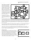
MONO SUM/GAIN CIRCUIT
Left and right input signals LCH and RCH are summed to mono
through R49 and R51. The mono signal is then attenuated in two
stages with dual potentiometer RV1 which is accessible from the rear
panel heatsink and serves as the gain control. R56 and R83 determine
the maximum achievable attenuation level. R59 and R66 help to
reduce the tracking errors of RV1 due to absolute resistance toler-
ances. Buffer U3B unloads the attenuators and provides 6dB of gain
with R25 and R73.
PHASE CONTROL CIRCUIT
The output signal of U3B goes directly to U4B if DS2 is left open
(0 degrees phase shift). If only DS2 is closed, the signal goes through 2
cascaded phase shift stages built around U6A and U6B, and
experiences a 270 degree phase shift. Additionally closing DS3 causes
the phase shift to be 180 degrees. Adding another closed switch DS4
results in only 90 degrees of phase shift. DS2, DS3, and DS4 are
labeled 2,3, and 4 respectively on the rear panel heatsink.
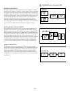
BUFFER/GAIN TRIM CIRCUIT
U4B works as a buffer, and as a factory gain trim using trimpot R136.
The voltage gain of the stage is (R74+R136)/R137.
FILTER CIRCUITS
U112A and U112B form two cascaded 2nd order variable low pass
crossover filters, for an overall 4th order 24dB/octave Linkwitz-Riley
response. The quad potentiometer R29 is accessible from the rear
panel heatsink and indicates the 40Hz–140Hz range of the variable
Low-Pass crossover. Following these circuits is a 2nd order subsonic
High-Pass filter at U2A. The signal then connects to the Class-G
amplifier.
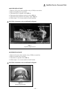
Qualified Service Personnel Only
TRM10.1/12.1 FUNCTIONAL BLOCK DIAGRAMS