


– 11 –
OPERATION
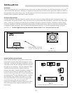
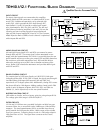
AUTO TURN-ON / SLEEP MODE
The TRM10.1/TRM12.1 subwoofers automatically turn on when they sense an input signal. When the signal being fed to the
TRM10.1/TRM12.1 is turned off, the subwoofer's amplifier will turn off and go into "sleep mode." This feature eliminates the
inconvenience of operating a mechanical switch.
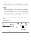
INPUT SENSITIVITY (GAIN)
The Input Sensitivity is used to match the TRM10.1/TRM12.1 with signal levels from a variety of mixing consoles. The Input
Sensitivity uses a variable potentiometer to match input levels over a 30dB range and is variable from 0dBu to -30dBu. The
numbers listed on the back panel indicate the input in dBu required to produce an output of 100dB SPL @ 1 meter. When the
control is set to its full CLOCKWISE position the monitor is matched to 0dB input level (the input circuit is less sensitive to the
amplitude of the input signal). When the control is set to its full COUNTER CLOCKWISE position the monitor is matched to
-30dB input level (the input circuit is more sensitive to the amplitude of the input signal).
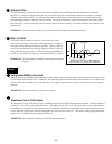
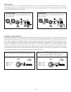
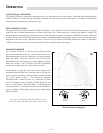
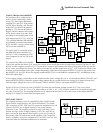
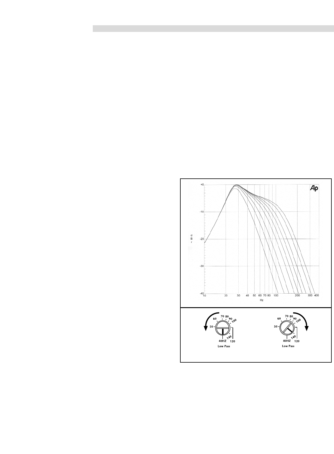
LOW-PASS CROSSOVER
The Low-Pass Crossover is used to set the electrical cutoff
point of the subwoofer enclosure. The Crossover uses a vari-
able potentiometer to set the cutoff point anywhere between
40Hz and 140Hz. When the control is set to its full CLOCK-
WISE position the cutoff frequency is set to 140Hz Low-Pass.
When the control is set to its full COUNTER CLOCKWISE
position the cutoff frequency is set to 40Hz Low-Pass.
It is important to match the Low-Pass crossover point of the
subwoofer with the High-Pass crossover point of the high fre-
quency reference monitors. Mismatching the crossover points
can cause peaks or dips in the acoustical response.
Overlapping the crossover points (i.e., subwoofer at 60Hz
Low-Pass & high frequency monitors at 50Hz High-Pass) will
cause a peak between 50Hz and 60Hz. Underlapping the
crossover points (i.e., subwoofer at 40Hz Low-Pass & high fre-
quency monitors at 70Hz High-Pass) will cause a dip between
40Hz and 70Hz.
*This graph was generated by setting the variable crossover to
40Hz, 50Hz, 60Hz, 70Hz, 80Hz, 90Hz, 100Hz, 120Hz & 140Hz.
Electrical Crossover Response*