


I NTRODUCTION
– 1 –
The Hafler 9303 and 9505 are two channel professional power amplifiers. Passive cooling with large heatsinks
is used for low mechanical noise. Our patented trans•nova circuit topology and MOSFET output stage ensures
trouble free, long term operation and is backed by our seven year warranty.
This manual contains information on using the 9303 and 9505 amplifiers. It is organized into three main
sections. “Installation” covers the location and connection of the amplifier in the system. Like many precision
components careful attention to the initial setup can yield dividends in higher performance and trouble-free
use. “Operation” covers the controls and features of the amplifiers and how to use them to get the best effect.
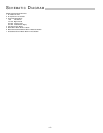
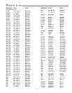
The “Technical Information” section contains information on the circuit implementation and the schematic
diagram and parts list. We strongly urge reading over the Installation and Operation portions of this manual
before putting the amplifier into service.
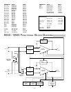
The circuitry used in the 9303 and 9505 is the latest refinement of our trans•nova (TRANSconductance NOdal
Voltage Amplifier, US Patent 4,467,288) circuit. The 9303 and 9505 utilize our proprietary DIABLO (patent
application in progress) transconductance driver stage which combines the linearity of Class A operation with
the current headroom of a Class B system. When used in combination with the robust output stage used with
these models, DIABLO yields lower high frequency distortion without the sonic penalties associated with
increasing the negative feedback.
The 9303 and 9505 have fully differential inputs for use in balanced line systems. The balanced input terminals
work with either 1/4" TRS phone or XLR plugs. Gold-plated RCA phono jacks are available for use with
unbalanced source components. The output terminals are gold-plated binding posts, spaced on 3/4" centers
for use with dual banana plugs. For high power applications, the amplifier can run in bridged mono for double
the output voltage. Using state-of-the-art surface mount assembly equipment in our manufacturing facility
ensures consistency and reliability.
LOCATION
The 9303 and 9505 can produce considerable heat in normal operation so the primary consideration when
determining a location for the amplifiers is to allow for adequate ventilation. The large heatsinks provide
unrestricted airflow, but care must be taken to keep the slots in the bottom panel and top cover clear, as well.
If the amplifier is mounted in an equipment rack, make sure adjacent equipment does not impede cool air flow
through the amplifier bottom and out the top. The attached feet provide sufficient clearance for the bottom
when the amplifier is resting on a hard surface. Inadequate ventilation can shorten component life, especially
when other equipment raises the ambient air temperature, so a circulating fan should be considered in tight
quarters. The power transformer can generate a substantial magnetic field, so caution should be exercised in
the placement of low level components such as a tape deck, mixer or mic preamp to avoid inducing noise in
the low level circuitry.
AC LINE
The 9303 and 9505 operate from a 120 volt, 60Hz AC power line. Connection is made by an IEC Type 320,
grounded line cord. For safety considerations only a properly grounded (earthed) receptacle should be used.
If a grounded circuit is not available do not break off the ground pin; use the proper adapter plug for a two wire
receptacle. Located inside the amplifier is the line fuse which interrupts the power to the amplifier. If this fuse
blows replace it only with the same type and rating fuse. The correct replacement fuse value is included in the
parts list in the “Technical Information” section of this manual. If the replacement fuse blows, this is an
indication of a fault with the amplifier. Servicing should be performed only by a qualified technician.
I NSTALLATION